OPTICAL MOUNTS: Stress-free mounting enables diffraction-limited performance
DONALD BARNHART AND ANN WILLIAMSON
Even under ideal environmental conditions, such as room temperature, standard atmospheric pressure, low humidity, and no vibrations, forces within optical mounts can deform optical components. Mirrors can warp and birefringence can be induced in lenses.
A year ago, a commercial cell sorter was under development at iCyt Mission Technology, a manufacturer of flow-cytometry equipment and biological cell sorters. The engineering team was in the laboratory looking at cells passing through a laser beam, but was not seeing the expected pulse profile. It appeared that the focus of the laser beam was being distorted by something in the optical system. The beam expander was the first suspect, but it turned out not to be the problem. One after another, each optical component was examined. After a week of testing and frustration, the problem was found in the last item left to examine: the optical mounts. A thin dichroic-filter mirror in the device had suffered stress-induced deformation by its mount.
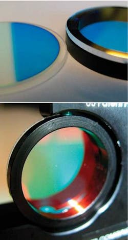
Dichroic-filter mirrors, used to selectively pass certain wavelengths of light while reflecting others, was being used in our system to combine different laser wavelengths into a common optical path. The filter was thin, just 1 mm thick, and 1 in. in diameter. It was found to be warped in the vicinity of the stress points of the mounts. Because there was no commercially available stress-free mount suitable for such an optic—it requires a wide-angle clearance—a mechanical engineer at iCyt, came up with a stress-free design for the mount that involved bonding an annular metallic retainer ring to the back of the rim of the filter (see Fig. 1).
The design distributes the stresses of the three-point mount evenly around the filter. Because stress (S) can be described by the equation S = P/A, where P is preload holding force and A is the area of contact, it turns out that increasing the area of contact can reduce the stress on an optic.1 Using the new stress-free mount, the engineer installed a replacement filter that suffered no warping and enabled the beam to focus correctly.
To further understand the influence of stresses on optical performance, one can simulate the effects of stressed optics computationally. Such a simulation usually involves two steps: first, calculating mechanical deformation and, second, calculating the resulting optical performance.
In many “real-world” systems, the mounting mechanism is complex and no simple analytic model for its behavior may exist. In such cases, it may be necessary to use a generalized numeric approach such as finite element analysis (FEA) or finite difference analysis (FDA) to accurately model the solid deformation.2 Both FEA and FDA methods involve breaking the object into discrete triangular mesh elements and then iteratively calculating how each element interacts with its neighbors and the applied stress boundaries. In general, such methods are time-consuming to set up and execute.
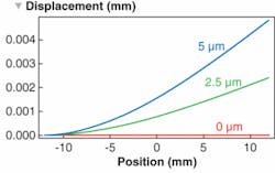
Sometimes, however, it is only important to estimate the overall impact of the stresses in the system rather than determine a specific stress-induced outcome. In such instances, it is sometimes possible to use a simplified analytic model of the stress-induced deformation. With this in mind, we have adapted the standard “cantilever” model to describe the localized one-dimensional bending of the stressed mirror element within iCyt’s instrument, called Reflection. In this case, the resulting mirror deformation can be given by a simple cubic polynomial equation:where dz is the resulting deformation at a point x along the surface and k is a constant to be determined.
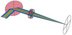
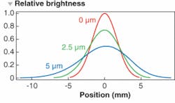
Having determined the stress-deformation in the optic, we can now use an optical modeling package developed by Optica Software to calculate the resulting system performance. In particular, our optical system consists of a Gaussian beam, a mirror with various degrees of bending according to the cantilever model, a lens doublet, and a screen at the focus (see Fig. 2). After incorporating the mirror deformation shape into the optical model, the system performance is measured by the coherent point-spread function at the focus for different amounts of cantilever bending (see Fig. 3). The shift and shape of the focus profile changes with different amounts of mirror-cantilever warping (see Fig. 4). In particular, we can see that the peak intensity at the focus is diminished by 50% when the mirror is deformed by 5 µm at its edge. In addition, the beam profile has become asymmetric and distorted. In some systems, such a deformation would be considered very large and therefore unlikely to occur. Unfortunately, with the thin optics originally present in our system, this amount of deformation would not be unusual.
Determining an appropriate mount for an optical component depends on a number of factors. The size, shape, and inherent rigidity of the optic are considered. Other factors include experimental sensitivity, tolerable movement, tolerable distortions, exposures to vibrations and shock, and the effects of changing temperatures. The long-term stability of the mount and the overall affordability in relation to the cost of the complete instrument is to be considered.
For some optics, off-the-shelf low-stress mounts are commercially available. For example, Thorlabs (Newton, NJ) offers a stress-free lens mounting that makes use of an O-ring together with a threaded retainer ring to hold the lens optic. The springy O-ring squeezes evenly against the edges of the lens to eliminate stress points. For large-aperture lenses, in which making threaded retainer rings would be difficult, flange-type retainer mounts can be used. Small mirrors can be mounted with flanges, cantilevered springs, spring-clamped mountings or bounded mirror mountings. Elastomeric rings can be used for mounting nonsymmetrical optics.
Flexure mounts are typically used for mounting optics subjected to adverse conditions such as extreme temperature changes, vibrations, pressure, and shock. The flexure mechanism provides elasticity and controlled relative motion that can keep a lens centered even after thermal expansion and can also correct for misalignments. Flexure mounts also allow the optic to return to the correct position and orientation after disturbances have subsided.
An amazing example of flexure use in mountings is the 12-flexure diamond-shaped lens mount for the lithium fluoride lenses (70–94 mm) on the Near-Infra Red Camera, an instrument for the James Webb Space Telescope.5 Lithium fluoride lens material was chosen for its outstanding performance in the near-IR (0.6-5 µm), but the material deforms plastically under even small tensile loading.6 So a mounting system was designed to withstand temperatures ranging from 300 K to 30 K (launch to cool-down) and to prevent the optic from plastically deforming from vibrations and shocks.
This was a difficult task, and after a failed attempt using a three-point flexure mounting-pad design, the mounting for the optic was redesigned using 12 diamond-shaped flexures around the circumference of the lens, each with metal flexure pads that interface the optic. Between the pads and the optic, a low modulus, compliant material was used to prevent metal-to-crystal contact. This finally met the stringent testing requirements. The James Webb Space Telescope is scheduled to be launched in 2013 as a replacement for the Hubble Space Telescope.
REFERENCES
1. P.R. Yoder Jr., Mounting Optics in Optical Instruments, SPIE Press (2002).
2. M.A. Bhatti, Fundamental Finite Element Analysis and Applications with Mathematica and Matlab Computations
3. P.P. Benham and F.V.Warnock, Mechanics of Solids and Structures, Pitman International, 1982, Third Edition.
4. Schott Technical Information TIE-27 Stress in optical glass (July 2004).
5. E.T. Kvamme, D. Trevias, L. Sokolsky, SPIE Optics and Photonics 5877, 33 (2005).
6. L.A. Ryder, L.W. Huff, SPIE Optics and Photonics 5904, 09 (2005).
Donald Barnhart is chief architect and optical scientist and Ann Williamson is senior software developer in the Optica Software Division of iCyt Mission Technology, 2100 S. Oak Street, Champaign, IL 61820; e-mail: [email protected]; www.opticasoftware.com.


