Steppers print high-quality long diffraction gratings
Step-and-repeat cameras (also called wafer steppers) are optical-projection tools that are at the heart of the photolithographic process used to fabricate microelectronics. Some steppers are currently used in specialized foundries for the fabrication of multilevel diffractive optical elements (DOEs). They have some limitations for this purpose, however. The first limitation—generally overlooked in DOE fabrication—is the field distortion caused by the residual aberrations of the sophisticated lens system. The second problem relates to the limited field size: when the area of the pattern to be transferred is larger than the field size (usually about 25 × 25 mm), the stitching error between the structures in adjacent fields becomes a major issue. This is especially true in the case of optical gratings, which can extend over a length of several fields.
Grating manufacturing technology has so far had little in common with microelectronic batch processes; it is still the domain of highly qualified artisans whose secrets are jealously kept hidden by a few suppliers. Lithography, however, is an open technology with established processes, controlled tools, high productivity and low costs. In addition, the shrinking feature size and larger-area wafers in current lithographic tools can allow the fabrication of high-efficiency gratings for the ultraviolet range and gratings of large size, respectively.
A group led by Olivier Parriaux at Jean-Monnet University (St. Etienne, France) has quantified the errors of step-and-repeat systems with a view to using them for the manufacture of large-area gratings. They have measured the regularity of the grooves of gratings intended for use in a displacement sensor by using the displacement sensor itself to make the measurements.
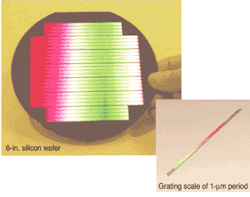
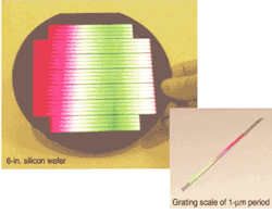
A wafer stepper made by ASML (Veldhoven, The Netherlands) was used to cover a 6-in. silicon wafer with an array of long reflective gratings (see Fig. 1). Measuring the regularity of grooves in those gratings provides an assessment of the quality of the stepper for step-and-repeat manufacturing of large-scale optics.
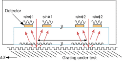
A grating with a period of 1 µm, for example, is used in a displacement sensor (see Fig. 2). The diffractive interferometric scheme has two small transmissive readout gratings of 0.5-µm period in close proximity to the long reflective grating and movable across the grating in the x direction.1 In one head, a normal-incidence collimated laser beam crosses the substrate and the readout grating and hits the reflective grating, generating 0 and ±1 diffraction orders. Because the period of the readout grating is half that of the reflection grating, light exiting in the directions of the ±1 orders of the reflective grating is actually a combination of radiation from the corresponding 0 and ±1 orders generated by the readout grating. These two interfering optical signals show sinusoidal modulations with respect to displacement in the x direction. Monitoring the radiation in both directions by two detectors and feeding their outputs to a differential amplifier produces the proper signal.
null
The absolute accuracy is primarily determined by the constancy of the stitching errors between fields. The effect of aberrations is a variation in grating period across the field, seen as an expansion or shrinkage of the supposedly strictly periodical measurement grid. The latter is the most damaging error—whereas stitching errors are random, aberration errors are cumulative, which is lethal for high-accuracy sensors.
Twin sensors
The spatial-frequency variations were measured with a differential scheme involving a pair of identical sensors spaced by a fixed distance. Such a scheme is exquisitely sensitive: whereas each sensor can easily resolve its position within 1 nm with a modest interpolation rate of 125 per phase quadrant, a phase difference of 1° between the two electrical signals supplied by the two sensors placed 10 mm apart as they fly over one of the grating tracks on the wafer corresponds to a period change of 1 picometer (pm). During a scan over a grating track, the two sensors see several identical fields; therefore, the longitudinal dependence of the period can easily be retrieved from the longitudinal relative phase variation.
It was found that the dependence is quasiparabolic, with an amplitude that depends on the position of the grating track in a projected field. The amplitude depends on which particular stepper is used. In the stepper under test, the maximum period variation was 22 pm and the minimum 10 pm. All fields exhibit very nearly the same variation. The stitching errors were below 10 nm, as was confirmed by "mortice-and-tenon" features at the stitching lines between adjacent fields.
It is therefore possible to test the regularity of a grating period and its possible chirp to a resolution of 1 pm. Thus, high-quality gratings of great length and large area can be finely characterized. The error can be calibrated—or, going a step further, can be corrected by using this characterization technique for performing a predistortion at the level of the lithographic photomask, opening the way to almost-perfect grating manufacturing. This technique can also be used to evaluate the manufacturability of gratings for spectrometers, pulse stretching and compression, add/drop filters, and structures for biosensors.
REFERENCE
- O. Parriaux et al., P. van Dijk et al., and S. Topcu et al., SPIE Intl. Symp. Optical Sci. and Tech. 4440, 209 (San Diego, CA, July 29-Aug. 3, 2001).


