Band architecture improves performance
The development and deployment of the erbium-doped fiber amplifier (EDFA) extended transmission distances of optical signals and opened a new era in optical communications. Prior to the EDFA, electrical repeaters regenerated optical signals every 40 km, making multiwavelength transmission prohibitively expensive. The EDFA allowed cost-effective deployment of dense wavelength-division multiplexing (DWDM) systems by replacing channelized electrical regenerators with a single device capable of amplifying "bands" of channels. This "banded" solution defined a business model to which optical equipment manufacturers should aspire: exploit the transparency and parallel processing capabilities of optics to increase performance and reduce cost of networks.
Much like time-division-multiplexed (TDM) signals, multiple optical channels of different wavelengths can be grouped in a band and more effectively managed at the band level. In SONET for example, 48 STS-1 signals are multiplexed to form an OC-48 signal (2.5 Gbit/s), four OC-48 signals form an OC-192 (10-Gbit/s) signal, which in turn are multiplexed into OC-768 (40-Gbit/s) signals. Aggregating individual wavelengths into bands, and managing the bands as discrete entities, is a continuation of this process. Optical networks can take advantage of photonic parallel processing to route bands of optical channels at costs not achievable through channelized electronic processing.
Wave-band architectures
Typically 80% of traffic at a given node is pass-through traffic. As such, grouping optical channels and performing functions such as grooming and switching in bands makes optical demultiplexing requirements less stringent, dispersion compensation more manageable, and optical switching and wavelength conversion processes more efficient. Fewer optical crossconnect ports are required to switch the same amount of traffic, so these new architectures can achieve significant reductions in port counts and per-channel cost of switching and wavelength conversion. As the number of channels in a band is increased, port count is reduced. A 1024 × 1024-port all-optical crossconnect (AOXC), for example, is reduced to 128 × 128 ports by using eight channels per band.
null
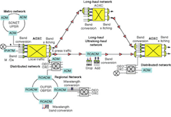
Using the available and emerging optical components and network equipment, a distributive-band optical network architecture can be developed (see Fig. 1). At core optical switching nodes, optical channels are multiplexed/demultiplexed and managed in bands rather than multiple individual channels. At the interface of the AOXC, wavelength conversion is performed in bands to eliminate blocking and manage wavelengths more efficiently. Bands rather than wavelengths are switched at the optical level, and express traffic is managed without unnecessary demultiplexing or optical to electrical to optical (OEO) conversion. Local traffic is directed to optical output ports, which have a band demultiplexer for individual wavelength granularity, and then to opaque OXCs or multiplexers, which provide finer levels of granularity in the electrical domain and route signals to the desired destination.
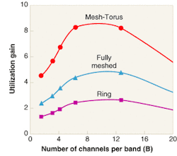
The benefit of wavelength conversion in band architectures depends on network size, topology, number of fibers, and the number of optical channels per fiber. The utility of wavelength conversion is measured by defining an interference length, L, as the number of links shared by two light paths, and a route length, H. Effective route length is defined by the ratio, H/L.1 Utility increases with effective route length (large H and small L) and network size, and decreases with the number of fibers and wavelengths per link. Utilization gain, defined as the ratio of network utilization with and without wavelength conversion, is calculated for a given blocking probability of less than 0.001 for a DWDM system with 64 channels.
Blocking probability (the likelihood of a signal being blocked) is reduced as the number of fibers increases, allowing a larger number of channels per band.2 An analysis performed for ring (H/L = 5), fully-meshed (H/L = 10), and mesh-torus (H/L = 20) architectures indicates that wavelength conversion provides greatest benefit in long-haul and ultralong-haul backbone networks, and dynamically reconfigurable mesh networks (see Fig. 2). Mesh-torus topologies benefit most from wavelength conversion because of high interconnectivity, long H, and short L. These results are equally valid in band network architectures, which effectively reduce the per-fiber channel count.
null
From a network utilization perspective, the ideal band structure (for 64-channel DWDM networks) is between 6 and 12 channels per band. From a cost perspective, 4 to 8 channels per band is ideal, depending on wavelength conversion costs. Therefore, 8 channels per band is a practical number of channels per band.
Band components
The critical requirements for optical switching devices are low crosstalk, to maintain the signal integrity, fast switching times for protection and restoration applications, low insertion loss, and scalability to support the design of large switching fabrics for AOXCs. Although high-port-count (256 × 256 and above) systems are difficult to deploy, 32 × 32- and 64 × 64-port devices as building blocks are available at reasonable cost. Band-managed networks leverage the optical parallel-processing capability of the existing switching technology to manage many wavelengths on a single port. Wavelength band switching therefore eliminates costly transponders.
Multiplexer/demultiplexers (mux/demux) have also enabled high-channel-count systems. The crucial differentiator between various mux/demux systems is the filter. Filters support both single-channel and band demultiplexing. Band demultiplexing actually provides better filter performance at a lower cost because there is a tradeoff between isolation, channel spacing (filter roll-off), insertion loss, and cost. Better isolation and closer adjacent channel spacing increases insertion loss due to the larger number of filter (cavities) layers required, resulting in higher cost.
Bandpass filters are simpler to design and more cost-effective than single-channel devices. Most existing OADM locations already use fixed band filters to add and drop bands of channels. Tunable filters support dynamic reconfigurability. Although they are not yet commercially available, emerging tunable filter technologies include acousto-optical, thermo-optic polymers, and microelectromechanical-systems.
Dispersion compensation is necessary in high-speed optical networks. At 10 Gbit/s (OC-192), chromatic-dispersion compensation is required to transmit signals beyond 60 km over standard single-mode fiber. With the emergence of ultralong-haul systems with regenerator-free distances up to 3000 km, dispersion compensation becomes vital to the deployment of 10- and 40-Gbit/s transmission systems. Dispersion-compensating devices have four key requirements: broad operating bandwidths to support many channels per band; low insertion loss; tunability to support dynamic functionality and accuracy; and dispersion-slope compensation to support many channels over long distances.
The dominant technology for chromatic dispersion compensation is dispersion-compensating fiber (DCF), which operates over the entire wavelength range of a system. However, it is a fixed solution. To compensate for slope over the entire wavelength range of a DWDM system, the wavelength range is divided into multiple bands at intermediate locations between transmission systems (typically every 400 to 500 km), to better match the dispersion slope for each band. Fiber Bragg gratings have the potential to offer tunability and slope compensation, but the technology is still in development and support of bands is limited by a narrow operating bandwidth (four channels at 100-GHz spacing).
Wavelength conversion
Recently there has been interest in developing all-optical wavelength conversion devices that eliminate wavelength blocking or collisions, improve wavelength management, and provide dynamic reconfiguration in DWDM networks. Ironically, most all-optical wavelength conversion technologies do not leverage the parallel processing capability of optics. Thus, wavelength conversion is currently accomplished by OEO transponders, which use a source laser at a different wavelength.
Several potential technologies for all-optical wavelength conversion are under development, including semiconductor optical amplifiers (SOAs), devices based on four-wave mixing in optical waveguides, and devices based on difference-frequency generation in lithium niobate. Wavelength conversion in SOAs is well known and research has been performed for many years. However, SOAs have not gained market traction because they typically have noise figures exceeding 8 dB, generate ripple on the pulse train at 10-Gbit/s or higher bit rates, and have limited transparency. Furthermore, high crosstalk limits SOAs to single-channel operation. Consequently they cannot support banded-wavelength conversion.
Wavelength converters based on four-wave mixing and third-order nonlinearities satisfy some requirements, including transparency and multichannel operation, but are limited by conversion efficiency and signal impairments such as "satellite" waves that can interfere with signal channels. These limitations prevent the support of bands of channels.
null
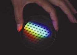
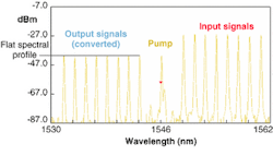
By lithographically patterning and processing lithium-niobate wafers in a semiconductor-type fabricating facility, a device which performs all-optical wavelength conversion is created. The result is a pure-optical chip, produced by a wafer-scale process (see photo, p. S7). Single or multichannel wavelength conversion is achieved in the optical chip through cascaded second-order nonlinear processes, which are driven by an ITU-grid semiconductor laser. The process is transparent, adding negligible noise or crosstalk. The wavelength converter chip is protocol and bit-rate agnostic, supporting existing (10-Gbit/s) and future (40-Gbit/s) high-speed network applications (see Fig. 3).
null
All-optical networks will not be deployed until they are cost competitive with the OEO-based electrical solutions. To further reduce the cost of optical networks, the photonics industry needs to move beyond "cottage industry" manufacturing practices, and develop automated manufacturing processes comparable to those of the electronics industry that take advantage of economies of scale to reduce the cost of optical components.
REFERENCES
- R. Barry and P. Humlet, IEEE JSAC 14(5), 858 (1996).
- S. Subramaniam and R. Barry, IEEE Int. Conf. Commun., 406 (1997).
LARRY R. MARSHALL is CEO and HECTOR E.ESCOBAR is director of product management at Lightbit Corp., 411 Clyde Ave., Mountain View, CA 94043; email: [email protected]; [email protected].


