Polarization plays a role in all reflection and scattering of light, and is an important parameter in many applications involving absorption and transmission. Determining the changes in the polarization state of a beam has been used for two centuries in measurements of great precision in a variety of sciences. Recently, polarization effects have been found to be a limiting factor in the performance of optical networks, as communications speeds move beyond 2.5 Gbit/s. Accordingly, analyzing the arbitrary polarization state of a light beam has become an economic concern of some urgency.
Although the scale of polarization effects in optical fiber may be less than parts per million, when accumulated over kilometers of fiber and numerous system connections, the resulting degradation of data integrity becomes significant. This degradation is primarily the result of polarization-mode dispersion (PMD), which produces a spread in the width of a digital signal pulse. At very high data speeds, the spread in pulse width smears the intervals between optical pulses, thereby degrading the signal.
The nature of polarization
The polarization of light is a somewhat obscure property, not detectable directly by the human eye (this isn't true for all animals—bees for example reportedly navigate by the polarization of sunlight scattered by the atmosphere.) Polarization refers to the direction of the transverse electric-field vector of the light wave. It is sometimes important to consider polarization from the viewpoint of light as a collection of photons, but this is beyond the scope of the current discussion.
To review briefly, light with its electric field oriented in a constant transverse direction, say x, is linearly polarized. Of course the amplitude of the electric field varies in time. If the field has equal x and y components that alternate 90° out of phase, the light is called circularly polarized (for right-circular light, the field appears to rotate clockwise to an observer looking into the beam; left-circular appears counter-clockwise).
Determining the direction of polarization is accomplished through the interaction of light with some anisotropic property of a material (which can be as simple as the angle at which the light strikes the material interface). Most molecules have some spatial asymmetry, and their electrons will be more responsive to the component of an applied electric field that is in the preferred direction.
The electric field loses energy in this direction as it performs work on the oscillating electrons, while a field component in an orthogonal direction is transmitted more freely. This is the origin of the birefringence that occurs in many materials, which have "fast" and "slow" indices of refraction. Light with polarization components in both directions will have its slow component delayed relative to its fast component as the light transmits through a birefringent material.
Obscure interactions
The basic concept of determining polarization is straightforward—an optical element called an analyzer that blocks essentially all of the light of a particular polarization is placed in front of a photodetector. Rotating the analyzer or combining two of them in series allows the simple polarization states of a beam to be inferred. The quality of the measurement is given by the extinction ratio, which divides the amplitude of the transmitted light by the leakage amplitude of the blocked polarization.
Polaroid sheet, a familiar means of aligning polarization, is essentially the molecular analog of a wire grid. Polymer chains are mechanically stretched in one specified direction and impregnated with a metal that provides the conduction electrons. Polaroid sheet was invented by E. H. Land while he was an undergraduate at Harvard, where he was inspired by the work of an English physician who studied the polarizing properties of dog urine.
The transmission of a polarized beam through birefringent or other optically active material can change the original state of polarization in complex ways. If the x and y components of a circularly polarized beam are made unequal, the beam now is said to be elliptically polarized. Allowing the amplitudes and phases of the field components to vary arbitrarily produces a still more complicated state.
Methods of representing an arbitrary state of polarization must be correspondingly sophisticated. The most general treatment is a column vector of four mathematically independent combinations of the x and y amplitudes called a Stokes vector (see Fig. 1). For light that is known to be polarized, the representation can be simplified to a two dimensional vector of imaginary amplitudes, the Jones vector.
null
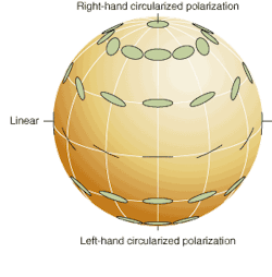
A representation that is growing in popularity is the use of the Poincaré sphere, which maps all states of polarization onto a spherical surface on which the north and south poles represent right- and left-hand circular states, respectively, while the equator stands for the orientation of linear polarization (see figure [right]). All of these mathematical representations are used by modern polarimeters, instruments designed to analyze an unknown state of polarization. Considerable effort has gone into the development of modern polarimeters to analyze PMD and other polarization-related losses in optical communications.
Polarization in optical networks
For a variety of reasons, a signal launched into a high-performance optical network is usually linearly polarized in a specified direction. Ideally, single-mode fiber is isotropic, and the signal emerges from the distant end of the network with its original polarization unchanged. In reality, stresses from installation, bends in the fiber, and temperature gradients all combine to produce birefringence in the fiber.
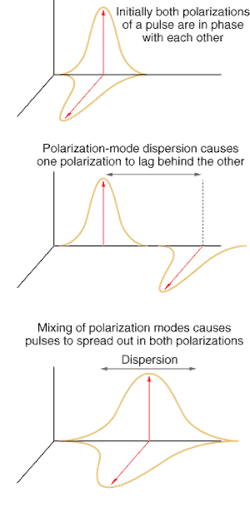
Because the stresses on the fiber are randomly distributed, net birefringence tends to cancel out over the total length of a fiber, but over shorter distances the effect is sufficient to produce a measure of elliptical polarization within that fiber region. This elliptical state now becomes the signal input to the next fiber length, which has a different birefringent orientation, and therefore produces still greater delay between the fast and slow signal components.
This is the origin of PMD, which is quantified in terms of the delay between the fast and slow transmission components experienced over a length of fiber (see Fig. 2). The delay itself is measured in picoseconds. To normalize for the length of fiber, this value is divided by the square root of the distance (the square root reflects the random distribution of the birefringence). Many existing networks were installed before PMD was a concern, and their performance as network speeds increase can only be determined through direct measurement.
null
Polarization-mode dispersion, like other forms of dispersion, is a function of wavelength, so a complete analysis of the performance of a network fiber requires determining the polarization response over the spectrum of the carrier. This is particularly true for DWDM communications. For the next generation of optical networks, the target for allowed PMD is only two to three picoseconds of delay end to end.
A variety of methods can be used to analyze the response of the fiber. A setup to measure the Jones vector of PDM-induced elliptical polarization supplies a spread of narrowband wavelengths with varying known states of polarization. The delay as a function of wavelength can then be calculated.
The method of coherent interferometry starts with lighting the fiber using polarized broadband light. The light at the output end is fed into an interferometer to produce an adjustable delay that is compared to the relative delay of the polarization components. The result is a determination of the average delay for the spectrum covered by the broadband source.
Selecting a method for determining PMD is often not straightforward, particularly in real networks in which different signals can be combined in a single carrier. Polarization-mode dispersion is one form of what is generally referred to as polarization-dependent loss (PDL), measured in decibels (dB). Network connections make a contribution to PDL as well, with losses from as little as 0.001 dB to as much as 0.3 dB depending on the type of interface.
Signs of life
Polarization measurements are also commonly used in the analysis of material properties. An ellipsometer measures the changes in polarization of light reflected from a thin film, allowing the determination of its thickness and index of refraction. Measurements can be performed only for flat surfaces, and if the film is metallic, it must be sufficiently thin so as not to absorb too much of the signal.
In an ellipsometer, light from a polarized laser is set at a known angle to reflect from the surface under test. The polarization of the incident light and its angle are varied until the reflected light at a measured angle is perfectly linear. These values are then used in Snell's equation to calculate the parameters for the film.
Many substances (quartz is one) possess a property known as "optical activity," meaning that they cause the electric field vector of linearly polarized light to rotate as it passes through the material. The molecules of these materials exist in two chiral forms that are mirror images of each other and cause the polarization to rotate in either a right- or left-handed direction. A fascinating example of this phenomenon involves the study of "chiral selectivity," which has been a puzzle since its discovery in the 19th century.
Known forms of life are overwhelmingly composed of amino acids with left-handed optical activity, and use sugars that are right-handed. One would reasonably expect an even distribution of left- and right-handed forms, as is found when these sugars and acids are made in the laboratory. In 1969 a meteorite was discovered in Australia that contained a surprising concentration of amino acids. Delicate measurements of their optical activity indicated the same preference for the chiral orientation as is found in terrestrial molecules, leading to serious speculation about an extraterrestrial origin for these building blocks of life. It remains, at the least, a question fundamental to understanding the origin of life on Earth.
Next month's article, the final one in this series, discusses the optical performance monitoring of communication networks.


