Speeding up transmission rates with slower signals

The goal of wavelength-division multiplexing is to multiply an optical fiber's transmission capacity by sending signals simultaneously at multiple wavelengths. In conventional dense WDM (DWDM), optical channels carry high data rates, typically 2.5 or 10 Gbit/s. Developers are still working on 40-Gbit/s technology, although their pace has slowed since the end of the telecommunications bubble.
A handful of developers are working on an alternative approach, called variously ultradense, super-dense, or hyperfine WDM. Instead of transmitting high-speed channels with a spacing of 50 or 100 GHz, ultradense WDM systems transmit slower signals on more closely spaced channels. The tighter channel spacing poses serious optical challenges, and the slower data rates require more channels to deliver the same capacity. However, advocates say that ultradense WDM offers some important advantages. Its slower data rates simplify the electronics required for transmitters and receivers, and avoid the need for added stages of time-division multiplexing. The slower data rates also avoid the serious dispersion problems suffered by higher-speed signals, particularly at 40 Gbit/s.
The limits to bandwidth
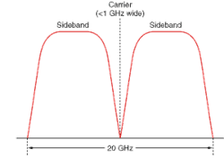
The same fundamental principles apply to both approaches to WDM. The maximum data rate possible on an optical channel depends on the modulation bandwidth of the transmitter source and the width of the optical channel. The act of modulation inevitably broadens the linewidth of a nominally pure carrier signal (see Fig. 1). Modulation with a simple binary NRZ (non-return-to-zero) signal at 10 Gbit/s creates a pair of sidebands that spread the signal across a 20-GHz range centered on the carrier frequency. (Higher-frequency components exist, have lower power and are more strongly attenuated, so they usually are ignored.) The two sidebands contain the same information, so one can be filtered out, but so far this has been confined to laboratory experiments. More complex modulation techniques, such as multilevel signaling, can compress a signal into a narrower bandwidth, but they require higher received powers, which lower the system margin.
Ultradense WDM and conventional DWDM systems can attain comparable spectral efficiency. Generally the peak spectral efficiency of state-of-the-art systems is about 0.4 bit/Hz of spectral width. Thus a 40-Gbit/s signal can fit into a 100-GHz DWDM channel, a 10-Gbit/s signal can fit into a 25-GHz channel, and a 2.5-Gbit/s signal can fit into a 6.25-GHz ultradense WDM channel. That means that all three approaches have the potential to transmit 1.6 terabits per second using only the C-band of erbium-doped fiber amplifiers. "Hero" experiments have operated at even higher spectral efficiency, reaching 1.28 bit/Hz and spanning more total bandwidth, but that technology is not yet practical.1
The choice between the two approaches to WDM boils down to deciding the tradeoffs between tough technical issues. During the bubble, top managers and industry analysts were pushing 40-Gbit/s transmission on each optical channel as the logical next step. Transmitting at 40 Gbit/s reduces the number of components needed per channel, but requires very sophisticated components to operate at such high speeds. Dispersion becomes a formidable problem at 40 Gbit/s. The magnitude of chromatic dispersion increases with the square of the bit rate because it depends on both the bit interval and the source spectral width—both of which increase with the bit rate. Polarization-mode dispersion also becomes increasingly important. Long-haul transmission at 40 Gbit/s is likely to require dynamic compensation for both chromatic and polarization-mode dispersion.
Sending slower channels through more, smaller slices of spectrum requires more components, more complex optical systems, and more careful stabilization of sources than transmitting fewer 40-Gbit/s channels. Yet ultradense WDM also offers some important attractions. Although slower channels require more components, they can use inexpensive mass-produced sources and receivers. The slower data rates greatly ease dispersion problems, and longer bit intervals reduce power requirements at the receiver.
A subtle but crucial issue is how well the two approaches match the signals that potential customers want to transmit. Current networks don't operate at 40 Gbit/s, so channels operating at that speed must be generated by time-division multiplexing slower input signals. Long-haul networks often operate at 10 Gbit/s, while 2.5 Gbit/s is generally the highest data rate in metro and regional networks, so carriers will have to consider multiplexing costs in their decisions. Lower-speed channels also allow carriers to upgrade capacity in smaller—and less expensive—increments.
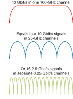
Two leading ultradense WDM approaches have emerged. Ciena (Linthicum, MD) has demonstrated a system that transmits 10 Gbit/s on 25-GHz channels, and says it will have a commercial version ready by the end of this year. That system is aimed at long-haul carriers that have already deployed 10-Gbit/s equipment. Essex (Columbia, Maryland) has demonstrated systems transmitting 2.5 Gbit/s on 6.25-GHz channels, which it is aiming at metro and regional carriers that now operate at 2.5 Gbit/s. Both are equivalent to a single 40-Gbit/s data stream in a 100-GHz channel (see Fig. 2).
Technology requirements
Two major technical issues face developers of ultradense WDM systems: slicing the spectrum into the fine slices they desire and keeping those wavelengths stable during system operation. Both considerations affect both light sources and the multiplexing/demultiplexing optics.
Single-frequency laser sources are already available. The challenge is to stabilize their wavelength in the center of the assigned channel. The laser frequency can be locked by reference to an external component. For example, Ciena locks the center wavelengths of the laser sources in its 25-GHz system to the narrow resonances reflected by fiber Bragg gratings. Like semiconductor lasers, Bragg gratings are temperature-sensitive, so the transmitters require a closed-circuit temperature control system to operate at the desired wavelength. Bandwidth of the modulated transmitter output depends on channel data rate and filtering optics.
Several optical technologies can multiplex and demultiplex closely spaced optical channels. Ciena picked fiber Bragg gratings for its 25-GHz system after evaluating thin-film filters and array waveguides. Ciena also used fiber gratings to demonstrate 12.5-GHz channel spacing. Advantages of fiber gratings include their sharp-edged, flattop transmission profile and the ease of adding channels when upgrading a system.
Other technologies promise serious competition. Wavesplitter Technologies (Fremont, CA) has demonstrated Mach-Zehnder interleavers with channel spacing as narrow as 12.5 GHz and shown that 25- and 50-GHz interleavers could be combined with a 40-channel array waveguide to demux 160 channels transmitting at 10 Gbit/s.2 They also have reported progress in reducing chromatic dispersion, which arises from the device structure and increases as the channel spacing is decreased.3
Complex designs are required to achieve 25-GHz channel spacing with thin-film interference filters. Cierra Photonics (Santa Rosa, CA) has demonstrated 25-GHz filters that contain five or six cavities, each containing about 40 layers of silicon dioxide and metal oxides. Low loss in the thin-film layers is critical because the normalized electric field is high in the cavities.4
Array waveguides can achieve even closer channel spacing and high channel counts, although insertion losses of experimental devices are high. NTT Photonics Laboratories (Kanagawa, Japan) have reported 160-channel array waveguides with 10-GHz spacing and insertion loss of 13 to 19 dB.5 More recently, NTT has made larger arrays with 512 channels and 12.5-GHz spacing, which it has used to transmit 2.5-Gbit/s channels through 320 km in the C- and L-bands.6
Essex has developed a proprietary optical multiplexer/demultiplexer based on technology adapted from Fourier optical signal processing. The company won't disclose details until its patent is approved, but did say is uses free-space optics that work like a multiport interleaver in part of the spectrum. For example, a 16-port version could slice a 100-GHz segment of the spectrum into sixteen 6.25-GHz channels, each directed to a separate lenslet that focuses that channel onto an output fiber. It can isolate channels as narrow as 50 MHz, but Essex initially demonstrated 6.25-GHz spacing. The optics are bidirectional, so a demultiplexer can be reversed to serve as a multiplexer.
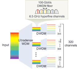
Like an interleaver, the Essex demultiplexer wraps around channels, so in a 16-channel device, a 17th channel would overlay the first. Because of this limit, it can subdivide only a small part of the spectrum—up to 100 GHz in current versions, with 200-GHz models in development. However, the ultradense demultiplexer can be combined with conventional DWDM optics to separate larger numbers of channels (see Fig. 3).
Systems and prospects
Several companies in addition to Ciena have tested ultradense WDM in systems transmitting 10 Gbit/s on 25-GHz channels. Alcatel (Plano, TX) has transmitted 160 channels at wavelengths between 1530.75 and 1562.44 nm through 380 km of fiber in tests of technology for submarine transmission, using remotely powered amplifier.7 NTT has transmitted 512 channels at 2.5 Gbit/s with 12.5-GHz spacing through 320 km of fiber, using both the C- and L-bands of erbium-doped fiber amplifiers. (Suzuki). Only Essex and its corporate partners are working on the denser approach—in addition to transmitting 2.5 Gbit/s on 6.25-GHz channels, they are working on systems to transmit Gigabit Ethernet on 3.125-GHz channels.
Ultradense WDM faces some significant technical issues. Both laser sources and multiplexing optics must meet rigid stability requirements to keep the channels separated. As with higher-speed systems, channel data rates are limited by the bandwidth of the channel. Experiments have shown that 10-Gbit/s transmission in 12.5-GHz channels is impaired by cross-phase modulation, while 25-GHz transmission is much better.8
Economic tradeoffs will also have to be made. Ultradense WDM requires many more transmitters and receivers than conventional DWDM. It's an open question whether the lower cost and ready availability of those slower devices will offset the higher costs of 40-Gbit/s transmitters and receivers and the dispersion compensation needed at those speeds. End users also will have to weigh whether they would prefer to stay with slower signals compatible with existing equipment, or multiplex to higher data rates. Those decisions may well vary among network operators and applications.
ACKNOWLEDGMENTS
Thanks to Michael Piacenza at Essex Corp., and Tom Mock at Ciena Corp.
REFERENCES
- S. Bigo et al., OFC 2001, Postdeadline paper PD25.
- J. Chon et al., 2001 Tech. Proc., Natl. Fiber Optic Engineers Conf., 1410.
- Andrew Zeng et al., OFC 2002, paper THC4.
- M. A. Scobey et al., OFC 2002, Paper ThC5.
- K. Takada et al., Proc. ECOC 2000, Postdeadline paper PD3-8.
- Hiro Suzuki et al., IEEE Photonics Tech. Lett. 14, 405 (March 2002).
- P. Le Roux et al., ECOC 2001, Postdeadline paper PD.M.1.5.
- E. Ciaramella, IEEE Photonics Tech. Lett. 14, 804 (June 2002).