WAVEGUIDE STRUCTURES: Subwavelength-grating crossing has low loss and crosstalk
An optical waveguide in a planar lightwave circuit can be designed to split into two or more waveguides; conversely, multiple waveguides can be made to merge. In this way, light can be split or merged as well. But often, two waveguides must cross while remaining optically isolated from one another. While several different crossing techniques have been developed, including resonant photonic-crystal structures, parabolic multimode-interference (MMI) sections, and others, each suffers from a drawback: for example, sensitivity to imperfection (resonant structures) or low-loss operation for only transverse electric (TE) and not transverse magnetic (TM) polarization (MMI structures).
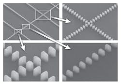
A type of waveguide crossing with low crosstalk and low loss at any polarization has been designed and experimentally tested by researchers from the National Research Council and the University of Ottawa (both in Ottawa, ON, Canada).1 The crossing relies on transversely tapered subwavelength gratings that cross at a small square block, with each grating including the block as one of its grating elements (see figure). Because the gratings are subwavelength, the block is not large enough to diffract light transversely, thus isolating the waveguides from each other.
Modeling versus experiment
The waveguides and gratings are fabricated from silicon dioxide (SiO2, with a refractive index of 1.444) on a base of silicon (with an index of 3.476). The subwavelength structure of the grating leads to an effective refractive index for the grating region that is lower than that for SiO2. Although the researchers realized that an optimal crossing geometry should have a length of 100 μm, their computer-modeling software could not simulate a structure of that length; as a result they could not model the theoretical efficiency of their fabricated structures (although they could measure an experimental efficiency). Instead, they modeled a shorter structure, which they knew would have a higher loss, and fabricated the longer structure.
In one example, a modeled structure had a linear chirp from 200 to 300 nm and a taper from an initial 450 nm to a final width of 200 to 350 nm (depending on the design) over 12 grating segments; this was followed by 8 constant segments with a 50% duty cycle. Improvements to some of the modeled structures included bridging segments, which contained grating segments superimposed on a solid but tapering portion of the waveguide. An example calculation showed crossing losses of -0.36 dB for TE polarization and -0.21 dB for TM polarization.
Insensitive to fabrication errors
The experimental crossings had long 50 μm tapered gratings with bridging segments and 350 μm grating sections with unvarying geometry. The researchers fabricated structures with varying numbers of crossings, including those with 0, 1, 5, 10, 20, 40, and 80 crossings; these were each created for two different crossing geometries. Due to a fabrication bias, the actual width of the subwavelength waveguide was 250 nm and the duty cycle was 33%, while the solid portion of the waveguide was 400 nm wide. In addition to these structures, standard wire-waveguide crossings (which are simply ordinary solid waveguides that cross) were fabricated for comparison.
Losses for the standard wire waveguides were -3.1 dB/cm and -3.2 dB/cm at a wavelength of 1.55 μm for TE and TM polarizations, respectively; these values helped the researchers separate the loss of their experimental crossings from those for standard waveguides.
For standard wire-waveguide crossings, the crossing losses were -0.975 dB and -0.763 dB for TE and TM polarizations, respectively. For a subwavelength grating crossing with a period of 300 nm at the crossing itself, the crossing losses were -0.023 dB and -0.037 dB for TE and TM polarizations, respectively–a reduction in the crossing loss of a factor of 30.
A tunable diode laser allowed the researchers to measure loss as a function of wavelength; while loss for the TE polarization remained relatively constant (less than 0.02 nm) over a 1520 to 1580 nm wavelength range, the measured loss for the TM polarization showed a 0.06 dB ripple due to a Fabry-Perot effect. Crosstalk was measured to be better than -40 dB, an improvement of 25 dB over the measured crosstalk of ordinary wire-waveguide crossings.
The researchers note that the subwavelength nature of their structures, and the resultant averaging of refractive index, reduces the effect of fabrication imperfections: For example, due to the fabrication bias, the fabricated grating elements were all reduced by 50 nm in size from the design sizes, but the crossings still performed very well.
REFERENCE
1. P.J. Bock et al., Opt. Exp., 18, 16146 (July 19, 2010).
About the Author

John Wallace
Senior Technical Editor (1998-2022)
John Wallace was with Laser Focus World for nearly 25 years, retiring in late June 2022. He obtained a bachelor's degree in mechanical engineering and physics at Rutgers University and a master's in optical engineering at the University of Rochester. Before becoming an editor, John worked as an engineer at RCA, Exxon, Eastman Kodak, and GCA Corporation.