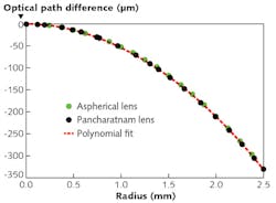
In a "Pancharatnam" phase-modifying optical device, the polarization state of a circularly polarized wavefront passing through the device is modified by the device as a continuous function of the position across the device. For example, a Pancharatnam lens is basically a half-wave retarder, with the retarder's local optical axis aligned with the azimuthal angle at that point. Such a lens—when designed as a positive lens for, say, right-handed, circularly polarized light—focuses light as a positive lens should, but becomes a negative lens when left-handed circularly polarized light is passed through the lens. Pancharatnam lenses have previously been fabricated by microrubbing, creating a space-variant subwavelength dielectric grating, or via holographic alignment. Now, a group at Kent State University (Kent, OH) has made an ultrathin (2.26 μm) f/2.1 Pancharatnam lens using a polarization holography alignment technique. The technique, which is low-cost, could be applicable to a wide size range.
Unlike a conventional diffractive lens, a Pancharatnam lens does not diffract light into undesired orders. However, like ordinary diffractive lenses, it does have a strong wavelength dependence. The researchers fabricated an experimental device for a 632 nm wavelength using a photoalignment layer that shows a strong orientational response to the local polarization axis of light, and is exposed in a holographic setup to provide the desired half-wave retarder orientation. The result is a polarization axis that is a function of the radial distance from the center of the pattern with a gradually decreased grating pitch to the edge. The design of the fabricated device had a parabolic phase profile and showed the expected imaging properties, which were good imaging quality for low f numbers and some degradation for higher f numbers. A design modeling the optimal diffraction-limited asphere would avoid the image degradation. Reference: K. Gao et al., Opt. Express, 23, 20, 26086 (Oct. 5, 2015).
About the Author
John Wallace
Senior Technical Editor (1998-2022)
John Wallace was with Laser Focus World for nearly 25 years, retiring in late June 2022. He obtained a bachelor's degree in mechanical engineering and physics at Rutgers University and a master's in optical engineering at the University of Rochester. Before becoming an editor, John worked as an engineer at RCA, Exxon, Eastman Kodak, and GCA Corporation.
