How mirrors, lenses, and prisms shape light systems
Snell`s law of refraction, the law of reflection, and the law of dispersion—basic optical principles we may have studied in high-school physics but long since forgotten—play critical roles in the manipulation of light. Even the most complicated optical designs must bow to these laws and incorporate either individually or collectively the fundamental elements of optics—mirrors, lenses, and prisms.
These laws were discovered empirically—from observing the refraction of the rays of the sun as it rose and set in the sky, or from watching the formation of shadows or the phases of an eclipse. From their observations, the early Chinese, Greek, and Arabian philosophers developed the science of geometrical optics—a method of studying light as rays instead of waves or particles. The rays are called paraxial because they are incident along or near the axis of an optical system; paraxial formulas have been devised to explain the behavior of the light rays.
The formulas with their theoretical explanations can found in most optics textbooks and in catalogs from optics manufacturers. This article takes a brief look at these formulas and describes their interaction with the most basic of the building blocks of optical systems—mirrors, lenses, and prisms.*
Mirrors: historical reflections
The mirror is perhaps the oldest optical element. Looking glasses were discovered in Egyptian pyramids built in 1900 BC. Plane, or flat, mirrors are found in practically every home today. Spherical, or parabolic, mirrors are often used in optical systems instead of lenses.
When a ray of light is incident upon a surface, components of the light are either absorbed or reflected. We see only the portion of the visible spectrum that is reflected. An apple appears to be red because all the colors (wavelengths) of the spectrum are absorbed at its surface except for red. A plant would die if exposed only to green light because it requires the absorption of all other wavelengths to generate chlorophyll.
This property inherent in mirrors, as well as lenses and prisms, is reflectance—the ratio of the light reflected from a surface to the total light reaching it. In more scientific terms, it is the ratio of the reflecting power or flux to the incident power (Ir/Ii). Reflectivity can vary over a wide range—from nearly 100% for metals that reflect visible and infrared wavelengths to nearly zero for highly absorbing materials.
The angle of reflectance of a ray of light is equal to its angle of incidence. This is the first law of reflection, originally determined by Euclid in 300 BC. The second law of reflection, credited to Alhazen, an Arabian optician, says that the incident ray, the reflected ray, and the normal must all lie in the same plane. Both of these laws of reflection are critical when determining where an image will appear (see Fig. 1).
Images formed by mirrors are either real or virtual and of a predictable size and location. A real image is formed when the intersection of the incident and reflected rays is in front of the mirror. A flat mirror produces a virtual image because the focal point, where all the incident parallel rays converge, is behind the reflective surface—each point of an object a given perpendicular distance from the mirror is imaged that same distance behind the mirror. The change is a 180° rotation about the optical axis, known as reversion.
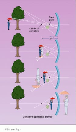
In addition to flat, the most common shapes for mirrors are convex and concave. These terms refer to the shape of the surface when looking along the direction of the incident light. A convex mirror, regardless of the position of an object, will always form a virtual, upright, and reduced image (see Fig. 2). An image produced by a concave spherical mirror is dependent on the location of the object in relation to its focal point.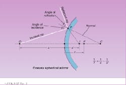
A concave spherical mirror has an axis of symmetry—the optic axis—through its center. A point on this axis equidistant from every point on the mirror`s surface is the center of curvature. An object beyond the center of curvature forms a real image between the focal point and center of curvature.
If an object is placed at the center of curvature, the mirror forms a real image that is the same size as the object but inverted. As the object is moved closer to the mirror, the image, though still real and inverted, moves away from the mirror and is larger than the original. When the object reaches a point halfway between the mirror and its center of curvature—the focal point of the mirror—the reflected rays from each point become parallel and no image is formed. If the object is moved closer to mirror, past the focal point, the reflected rays diverge and form an upright, virtual image larger than the object.
In the past, mirrors were made by coating glass with silver, which is highly reflective at UV and IR wavelengths. Vacuum-evaporated coatings of aluminum on highly polished substrates are now the accepted standard for quality mirrors.
Lenses: light bending
Lenses have had a relatively long evolution. Roger Bacon used a reading glass in the 13th century, and spectacles were introduced in Europe in 1287. But it wasn`t until some 400 years later that the microscope was invented, followed by the telescope a decade or so after that.
The governing law for the operation of lenses is the law of refraction, or Snell`s Law. This calculation determines how much light is bent, or refracted, as it passes from one medium to another, such as sunlight passing from air into water or from air into a lens. Light is refracted when there is a change in its speed. The greater the optical density of the medium that the wavelength enters, the lower the speed of light through the medium. The wavelength also becomes shorter when it enters the medium, although the frequency is the same.
Snell discovered two important points for determining how much the ray will be bent--that the incident and refracted rays lie in the same plane and that the refracted angle can be calculated by
n1sinQ1 = n2sinQ2
where n1 = index of refraction of the first medium, Q1 = angle of incidence in the first medium, n2 = index of refraction of the second medium, and Q2 = resulting angle in the second medium.
In its most simple form, a lens is a single curved surface that collects light from a source and refracts that light to form a usable image of that source. Our eyes do this. Usually, a lens consists of two or more transparent refracting interfaces, at least one of which is curved. Depending on its curvature, a lens will cause light either to converge or diverge. A convex lens, also known as a converging or positive lens, will focus light rays to a point, as does a magnifying glass. It will always be thicker in the center than at the edges. A concave, diverging, or negative lens disperses light and is thinner in the middle than at the edges.
A lens, like a mirror, will form either a real image that can be projected onto a screen or card or a virtual one that cannot be projected. Also, as with a mirror, an image from a lens can appear either upside down or right side up. A convex lens inverts the image; a concave lens does not. Most astronomical telescopes use convex lenses. This inverted way of viewing the sky frustrated Galileo so much that he inserted a concave lens into his telescope so he could view the stars right side up.
The cornea of the human eye is a convex lens that refracts light coming through it, focusing it into inverted images on the retina. The inverted images are conveniently turned right side up by the brain. Larry White, director of the Needham Science Center (Needham, MA), described an experiment in which a group of people were asked to wear prism glasses for a period of time. The prism in the glasses turned the image coming to the cornea upside down, and the cornea sent it right side up to the retina. The brain naturally reversed it, again turning it upside down. Interestingly enough, the brain soon adjusted to this new way of receiving information and stopped reversing the image. When the people stopped wearing the prism glasses, they again saw the world upside down until the brain readjusted.
The behavior of a convex lens is similar to that of a concave mirror in that the place where the image is formed is dependent on where the object is in relation to the focal point. The equation used to calculate the focal length of a convex lens is the same as that used for mirrors (see Fig. 3).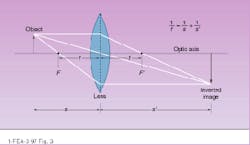
A concave, negative lens by itself cannot form a real image as a positive lens can. Light passing through a negative lens parallel to the optic axis is bent away from the axis. The focal point of the negative lens is located by extending these diverging rays backward until they cross the axis. The image formed by a diverging lens is always virtual, upright, smaller and closer to the lens than the object. Negative lenses are used to reduce images and to construct compound lenses.
When an optical engineer asks, "Which lens should I use?" he or she begins by defining the problem—noting critical quantities such as magnification, focal length, clear aperture (diameter), and object and image position by applying the paraxial formulas with the known parameters and solving for remaining values such as the f-number, numerical aperture, and element diameter of the system. These are purely geometrical values, determined by paraxial equations, that tell nothing about the quality of the image produced, but they do provide an idea of how feasible the task is. Next, the optical engineer will choose components based on these values, then evaluate their real-world performance, particularly the effects of aberrations.
The imaging capability of a real optical system is diffraction-limited, never perfect. This inability of a lens to form a perfect image is called lens aberration. Mirrors are also susceptible to this phenomenon. Common lens aberrations are spherical, coma, field curvature, astigmatism, distortion, and chromatic. A spherical aberration occurs, for example, when you have a converging lens or mirror that cannot bring parallel rays into focus. This is usually because the focal length for rays focused by the central part of the lens differs from that for rays focused by the outer parts, and a fuzzy image is formed. Compound lenses are often used to minimize aberrations.
Prisms: color components
In the early 1600s, missionary reports from Asia indicated that prisms were well known and highly valued in China because of their ability to generate color. But it was left to Sir Isaac Newton to explain that, despite popular belief, the prism did not create the colors but only made visible the components of white light through the process of dispersion.
Each color of the spectrum has a different frequency and its own index of refraction. As incident white light enters a solid, each of its component wavelengths is bent according to the index of refraction of the solid. But this refractive index is also wavelength-dependent, causing the shorter wavelengths (those with a higher refractive index, such as blue) to bend more than those with a lower refractive index (such as red). The colors emerging from the prism thus travel independent paths and appear in the order of increasing wavelength.
Prisms are also used to redirect light by refraction or internal reflection. The amount a ray is bent depends on the apex angle of the prism, the angle of incidence of the light, and the refractive index of the prism material. When a ray strikes the entrance face of the prism, it is refracted toward the normal. As the ray continues through the prism and strikes the outside wall and emerges into air, it is further refracted, following Snell`s law. The ray is bent away from the normal because air has a lower refractive index, allowing the wavelength to resume its normal speed. The angular difference between the ray`s original path and its new direction is called the angular deviation. The greater the refractive index, the greater the deviation. The deviation is least when the ray passes symmetrically through the prism.
Total internal reflection is an important property of some prisms. A beam is introduced in such a way that at least one internal reflection takes place for the specific purpose of either changing the direction of propagation or the orientation of the image or both. Rays internally incident upon an air/glass boundary, at angles greater than the critical angle are reflected with 100% efficiency regardless of their initial polarization state. This reflection efficiency is better than that achieved by many mirrors. Total internal reflection occurs only when light originates in a medium of greater optical density, such as light passing from water to air. In a reflecting prism, dispersion is not desirable.
By themselves, prisms are incapable of forming real images (see Fig. 4). If an imaging optic is not present in the system, the emerging image will be virtual. It will have the same orientation as the real image, but it can be seen only by looking back through the prism.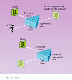
Examples of more-specialized prisms include corner-cube reflectors, penta prisms, roof prisms, and porro prisms. Corner cubes reflect any beam entering the face, regardless of orientation, making them useful for applications in which precision alignment is difficult. Penta prisms are useful in rangefinders and movie cameras; they reflect light through 90° by two reflections without inversion or reversion of the image. Roof prisms erect an image and bend the line of sight through 90°. In refracting astronomical telescopes they erect images. Porro prisms are pairs of narrow right-angle prisms that are used in binoculars and telescopes; they erect and revert an image as well as shorten the length of an instrument.
* Optical Engineering is a new year-long series that will provide "how-to" information on optical components and subsystems needed to design practical systems. The first few articles describe the basic principles of simple components--mirrors, lenses, prisms, filters, and gratings; later articles will examine subsystems for applications such as spectroscopy, radiometry, and imaging.--Ed.
About the Author
Laurie Ann Peach
Assistant Editor, Technology
Laurie Ann Peach was Assistant Editor, Technology at Laser Focus World.