In the past decade, fiberoptic communications have grown into one of the two major media for long-distance phone and data communication, rivaling, and in some ways surpassing, the use of communications satellites. At present, plans are rapidly evolving that will put fiberoptic lines into every neighborhood and perhaps, eventually, into individual homes. The carrying capacity of such fibers is now closely approaching the limits set by the physics of the fibers.
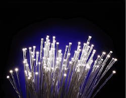
Fiberoptic cables for telecommunications came into widespread use in the 1980s. The first transatlantic optical-fiber system was installed be tween the USA and Europe in 1988, with a capacity of 300 Mbit/s, or 8000 phone channels. Today, planned intercontinental fiber cable will soon have capacities of 10 Gbit/s per fiber, nearly 100 times more than before. This increase is mainly due to advances in the design of the optical cables themselves (see photo at top of this page).
Reflecting on basic principles
The physical phenomenon underlying all fiberoptics is total internal reflection. When a medium of high refractive index is surrounded by one of lower refractive index, light approaching the boundary at less than a critical angle will be completely reflected, with no transmission losses. Thus, repeated reflections from the sides of an optical tube or fiber will not lead to the attenuation of the light.
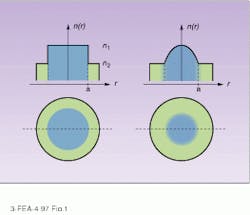
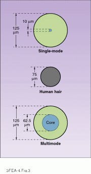
In an optical fiber, the high-index material is glass, while the low-index material is a surrounding cladding. The cladding is typically also glass but with a slightly lower refractive index. This ensures that only light rays with a reasonably low angle relative to the fiber surface are reflected, and, therefore, that the dispersion due to different path lengths is minimized. The earliest types of fiber were step-index types, where the index of refraction was level across the entire core. This meant, however, that rays traveling close to the axis had shorter path lengths and thus shorter travel times than those at an angle to the axis. Such dispersions limited early fibers to data rates around 15 Mbit/s/km, precluding long-distance use. The solution to this problem was the graded-index fiber, in which the index of refraction increased in a smooth curve toward the axis (see Fig. 1). Rays traveling along the axis thus traveled slower, making up for the path-length difference with the off-axis rays.The cores of optical fibers are made of ordinary glass, or silica, which is produced with extremely low impurity levels, because impurities will tend to scatter and absorb light. The surrounding clad ding, typically fluorine-doped and 125 µm in diameter for both multi- and single-mode fibers, is in turn surrounded by strengthening materials, either Kevlar or nylon, and the fibers are bound together into a cable reinforced by steel strands. All this material is generally protected by copper and polyethylene sheathing.
Attenuation losses
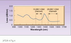
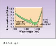
As light travels through the fiber, it is vital to minimize absorption and scattering so as to maximize the spacing between re peaters. Once impurities such as transition metals and hydroxyl (OH) ions have been essentially eliminated, two basic processes limit transparency. One is Rayleigh scattering off the disordered lattice structure that is characteristic of all glass. Rayleigh scattering, responsible for the blue color of the sky, drops steeply as the inverse fourth power of the wavelength. However, at wavelengths beyond 1.6 µm, infrared radiation can be coupled into the absorption band of the silica itself, producing band-edge absorption, which rises steeply with increasing wavelength. Another smaller intrinsic absorption line produces a bump near 1400 nm. The net result is that there are two minimum-absorption wavelength bands--a narrow one around 1300 nm and a broader, lower one around 1550 nm (see Fig. 4).For single-mode fibers, attenuation is typically around 0.2 dB/km at 1550 nm and 0.35 dB/km at 1300 nm. Values for multimode fibers are about twice as high. This is an extremely high level of transparency: 0.2 dB/km means that the light must penetrate 50 km of this glass to lose 90% of its intensity, transparency comparable to that of the clearest atmosphere at sea level.
Spreading the pulse
Aside from attenuation, the main limitations on the information-carrying capacity of single-mode optical fibers are the remaining types of dispersion after multimode dispersion is removed. The most important of these are waveguide dispersion and material dispersion. Waveguide dispersion is related to the fact that in single-mode fibers a significant fraction of the optical power actually propagates though the inner layer of the cladding, which has a lower refractive index than the core. Because the fraction of power in the cladding varies with the wavelength of the radiation, so does the effective index of refraction and thus the velocity of propagation. Signals of slightly different frequency thus tend to separate as they travel.
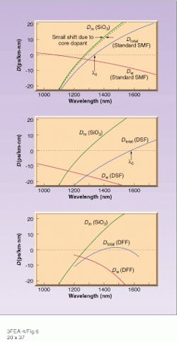
Similarly, any material, including silica glass, has an index of refraction that varies with wavelength, so again a separation with wavelength occurs over long distances. Together, waveguide and material dispersion are termed chromatic dispersion. Waveguide dispersion decreases with increasing wavelength and is negative for wavelengths beyond 1000 nm, while material dispersion increases with increasing wavelength and is positive for wavelengths beyond 1250 nm. There is thus a wavelength of minimum dispersion, l0, where the two effects cancel out. A perfect cancellation is not achieved because zero dispersion exists only at an exact wavelength, and a signal of any finite bandwidth will still suffer dispersion.
For standard single-mode fiber, l0 is about 1310 nm, just at the first minimum in the attenuation. Here, the two dispersions both have values of about 3 ps/nm-km, which would allow about 130 Gbit/km for a bandwidth of 2.5 nm, or 300 GHz. But with the cancellation, which improves with decreasing bandwidth, the actual dispersion is around 85 fs/km-nm2 leading for the same bandwidth to a capacity of 1800 Gbit/km. In both cases we are, of course, ignoring the effects of attenuation.A more complex approach is dispersion-flattened fiber in which the dispersion is low over a wide range of wavelengths and there are two dispersion minima--one at 1550 nm and one at a shorter wavelength. In these fibers, there is a steeper increase in the negative waveguide dispersion with wavelength, flattening out the total dispersion and keeping it below 2 ps/km-nm through the whole wavelength range from 1350 to 1600 nm. At the 1550-nm minimum, the rate of change of dispersion is still further reduced to less than 40 fs/km-nm2. Dispersion flattening is accomplished by fibers that have alternating rings of higher- and lower-refractive-index material, produced by carefully controlling doping levels.
Solitons simply compensate
There is a possible way to eliminate dispersion entirely, although it is not yet in commercial use. This is the phenomenon of solitons, or stable waves. Solitons can exist in many oscillatory media, but in optical fibers they are based on the Kerr effect. In this effect, present in silica glass, the refractive index is increased by a small term proportional to the square of the electric field (or the power level of the radiation).
For a sufficiently strong and appropriately shaped pulse, the dispersion due to chromatic factors can be exactly balanced by the Kerr effect, because the highest-frequency components of the pulse are also the highest-amplitude components. So when chromatic dispersion is negative—in silica at wavelengths longer than 1.3 µm, solitons can form and remain stable indefinitely, as long as attenuation does not reduce the strength of the pulse below a critical level. Thus, such soliton-based communication would be limited by attenuation alone.
System considerations
From the standpoint of the design of telecommunications systems, the key parameters are bandwidth and the spacing of repeaters or amplifiers. Attenuation and dispersion for the most part determine those parameters. In addition, of course, the better the detectors and the more powerful and well-controlled the lasers, the better the system performance. Basically, at relatively low bandwidth, attenuation is limiting, because it causes the signal to deteriorate below the level that it can be detected at high signal-to-noise levels. This limit tends to decline slowly with increasing bandwidth. However, at high bandwidths, dispersion becomes the limiting factor.
For example, for dispersion-shifted fiber at 1550 nm, repeater spacing is attenuation-limited up to about 1 Gbit/s, with a maximum spacing of roughly 200 km. Above that, dispersion makes repeater spacing inversely proportional to bandwidth, dropping to 10-20 km at 10 Gbit/s. Repeater spacing tends to be about half as long for 1300 nm. The narrowness of the underlying laser carrier can further cut dispersion. In general such considerations dictate the use of 1550 nm for the longest-haul lines and 1300 nm for shorter links.
About the Author
Eric J. Lerner
Contributing Editor, Laser Focus World
Eric J. Lerner is a contributing editor for Laser Focus World.
