Projection optics for lithographic steppers are typically complex, expensive systems formed of precision components and cost in excess of $1 million. These objectives must provide maximum throughput while producing a well-corrected, high-resolution image at the wafer plane. System performance should not degrade significantly with time. Required lifetimes are on the order of ten years, with wafer fluences on the order of 1 mJ/cm2/pulse.
Lithographic objectives for i-line and 248-nm steppers require optical materials of high transparency and homogeneity. With the shift to 193-nm source illumination, however, optical materials have become the critical issue. At this wavelength, most materials are highly absorptive and prone to optical damage. A number of alternate materials are hygroscopic, birefringent, or otherwise unable to support the high-performance requirements of lithographic objectives.
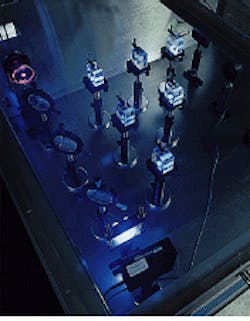
Two materials have emerged as the primary choices for the 193-nm wavelength—fused silica and calcium fluoride. Well characterized, easy to fabricate, and thermally stable, fused silica is in many ways the material of choice for 193 nm. Initial fused silica samples under study showed significant absorption losses, and intense excimer laser illumination created high levels of optical damage (see Fig. 1). These were not, however, the only issues.
During testing of a fused silica lens early in the 193-nm lithography development program, Massachusetts Institute of Technology Lincoln Laboratory (MITLL; Lexington, MA) researchers inspecting the exposed lens between crossed polarizers discovered an annular region of stress fringes around the edge of the beam footprint. Upon further study, the effect proved to be caused by compaction—impinging photons in the beam literally densified the fused silica, changing the figure of the optical element and introducing phase errors.
The process of compaction is not fully understood. Optical doses break and reform bonds in fused silica and cause the atoms to move around, compacting the material structure. Although the effect is a quadratic function of optical intensity, for a given intensity, damage increases with total sublinearity; groups at the University of California at Berkeley, Corning Inc. (Corning, NY), and MITLL have shown the exponent to range between 0.6 and 0.7.
Compaction has been a real concern to optical developers, says Mordechai Rothschild of MITLL. Although initial studies seemed to suggest that compaction was a material-independent phenomenon, Rothschild says that grades of fused silica intended specifically for 193-nm lithography have shown resistance to the effect. "One can reduce the level of compaction apparently without sacrificing other properties," he says. The question of how much compaction is allowable has yet to be determined, but Rothschild is reassuring about the final implications. "Given what we know about scaling laws and recent improvements in fused silica, compaction will not be a show-stopper," he says.
Meanwhile, fused silica has been manufactured with absorption coefficients of 0.002 cm-1, nearing the goal of 0.001 cm-1. Index inhomogeneities have dropped to 0.5 × 10⁻⁶, twice as good as required, and strain birefringence meets goals.
Calcium fluoride
Talk to anyone associated with 193-nm stepper or projection optics development, and the subject of calcium fluoride (CaF2) is bound to come up. Calcium fluoride is the other optical material to play a significant role in 193-nm objectives. It is highly transparent to that wavelength and, unlike fused silica, is a single-crystal material and therefore not subject to compaction.
Calcium fluoride is essentially the only material that can be used in conjunction with fused silica for color correction in all-refractive systems. Such dual-material refractive systems can minimize the spectral line-narrowing required of ArF lasers for deep-ultraviolet lithography, but they will not eliminate it entirely. In 248-nm objectives, for which more data are available, refractive systems relying on CaF2 for color correction require laser linewidths on the order of 1 pm. Comparable catadioptric designs can operate with a source linewidth of 300 pm.
Despite the benefits, calcium fluoride has its share of drawbacks. It is pressure sensitive, with a high coefficient of thermal expansion. These characteristics, along with the single-crystal nature that renders CaF2 immune to optical compaction, make the material extremely difficult to fabricate to the levels of smoothness required. "It polishes terribly," says John Bruning of Tropel (Fairport, NY). "You can make a good surface in it, but it`s not easy. It`s also nowhere near the same level of maturity as an optical material as fused silica."
There are also concerns about supply. "There is no question in my mind that there will be struggles to make the quantities necessary," says John Shamaly of SVG Lithography (SVGL; Wilton, CT). "If we use the material, it will be in small quantities." David Shaver of MITLL agrees. "The area I`m most concerned about is still the optical materials area—ramping up a global supply of high-quality CaF2 may test industry capabilities."
Optical designs
Difficulties in developing sufficiently line-narrowed ArF lasers have forced designers to produce color-corrected, or achromatic, systems. There are two design options for 193-nm projection optics: all-refractive systems and reflective/refractive (catadioptric) systems. The two schools of thought are split along the dividing line of color correction and use of calcium fluoride.
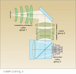
In the catadioptric systems, most of the optical power in the system lies in the primary mirror (see Fig. 2). Most of the elements are fused silica; designs may contain CaF2 components, but only sparingly. Catadioptric designs typically contain a dozen or so elements; more-traditional all-refractive designs contain more than twice as many components. For example, the objective in the ISI 10X reduction small-field stepper, produced by Tropel, is a six-element catadioptric system with a numerical aperture (NA) of 0.6 and a 2.1-mm field; all lenses are fused silica (see Laser Focus World, Feb. 1997, p. 75). To circumvent glass-damage issues, the design contains no beam crossover in the classic sense, spreading out the energy to avoid compaction. Tropel is currently working to develop a 0.75-NA system with a larger field size for use in process development applications.The prototype full-field 193-nm stepper built by SVGL for MITLL features a 4X-reduction catadioptric system with an NA of 0.5 and a 22 × 32.5-mm field. SVGL holds patents on several catadioptric systems for 193-nm lithography. The company is currently developing full-field lenses for production-level use.
Meanwhile, manufacturers such as Nikon Precision (Belmont, CA) are investigating all-refractive systems. "It`s a natural approach for Nikon to continue to use refractive designs," says John Wiesner of Nikon. "We have tools, background, and manufacturing knowledge, so we`ll start there."
Fabrication and metrology
The challenging part is being able to manufacture the lenses as close to the design specifications as possible. "Advanced illumination techniques really only work when you`re close to perfect," notes Tropel`s John Bruning. Although not impossible, optical fabrication for 193-nm components is nontrivial. Figure requirements are exacting. Short-wavelength illumination is easily scattered, so surface finish requirements are on the order of a few angstroms rms. Image quality is also vulnerable to degradation by scattering from mid-spatial frequency roughness.
Metrology for 193-nm components also becomes an issue. Although in the fabrication phase, some companies are getting good results with modified helium-neon-laser-based interferometers or metrology systems based on 248-nm sources, ideally components should be tested at the operating wavelength. Certainly to attain the required performance, assembly and alignment must be monitored at 248 nm or 193 nm. Metrology with excimer lasers is complicated by the pulsed nature of the sources and the short coherence length, but companies such as SVGL, in collaboration with MITLL, have developed 193-nm interferometers, and Tropel engineers have been getting good results with 248-nm-based instruments.
Finally, components require coatings robust enough to stand up to billions of optical pulses. Although materials have been the primary issue in development programs like the one at MITLL, degradation of optical coatings at high intensities has concerned some designers. "Lifetime isn`t a big deal with laser or beam-delivery optics," says Mordechai Rothschild. "Those components are easily replaceable in the field. But you don`t want problems in the projection optics."
Unlike solid-state ultraviolet lasers for medical applications, lithography sources provide relatively homogeneous beams with flat-topped profiles, so the issue is more one of coating lifetime rather than localized damage regions. In addition to optical damage, coating integrity can be compromised by internal stresses in the substrate, such as those caused by compaction. Coating smoothness is not generally thought to be an issue.
Getting tougher
Nevertheless, manufacturers and research groups have made significant progress with thin-film robustness. For example, coatings from Alpine Research Optics (Boulder, CO), produced by a proprietary electron-beam deposition method, have withstood 5 million shots at 200 mJ/cm2 with no observable damage. Pulse durations were 20 ns at 100 Hz. At MITLL, coatings have survived approximately 20 million pulses at 100 mJ/cm2 without visible damage.
To compress durations, testing is generally performed at higher fluences than expected for production-line steppers. Test data can be misleading, as intense ultraviolet illumination creates ozone that may degrade coatings. "In testing, we need to reduce the fluences and go to more pulses," says Rothschild. "Production-level parameters are more like four to ten billion pulses per year at 1 mJ/cm2.
The optics community is gradually overcoming such technological hurdles as it deals with the significant challenges from 193-nm lithography. Issues of supply are still a concern, given the sheer number of lenses that will be needed as the 193-nm generation comes on-line. "It`s going to be difficult to get the industry the quantity of tools [it will need] in the necessary time frame," observes Larry Thompson of ISI. Still, the consensus is that the projection and illumination optics will not significantly retard the deployment of 193-nm lithography.
A useful diagnostic tool
A photosensitive film inserted in the beam line to capture the stepper illumination pattern at the wafer plane shows the lines of a typical photoresist test pattern. The UVSC-365 SensorCard from SensorPhysics (Oldsmar, FL) is sensitive to illumination from 0.8 to 500 nm and produces images almost instantly and without any development process, giving stepper developers and semiconductor manufacturers a useful diagnostic tool for understanding system performance. Image color varies as a function of incident intensity. By digitizing the images, users can obtain quantitative information about illumination intensity and uniformity, as well as edge effects. The material offers spatial resolution on the order of 0.1 µm and can be used for illumination profiling anywhere along the beam line.
About the Author
Kristin Lewotsky
Associate Editor (1994-1997)
Kristin Lewotsky was an associate editor for Laser Focus World from December 1994 through November 1997.

