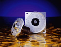
Laser scanners are ubiquitous in barcode scanners at retail check-out lines and in laser printers in offices and homes. One of the most recent Xerox product lines, a multifunctional digital office machine that copies, scans, and prints documents as well as faxing them, owes its existence to a new generation of high-speed, miniature polygonal scanners (see photo at right; see also "Smaller scanners lead the way," p. 117). In addition to their use in common business applications, laser scanners are important components of display systems, visual inspection devices, medical and infrared imaging systems, micromachining, and plate making.
Much to the chagrin of motorists, a laser-scanner-based vehicle-detection system provides three-dimensional images of speeding motorists and toll evaders. A family of Autosense products from Schwartz Electro-Optics Inc. (Orlando, FL) incorporates an infrared dual line-scanned laser rangefinder with a polygonal scanner to identify vehicles and their lane position. Classification, height, length, width, and speed of both cars and trucks can be profiled (see Fig. 1).CID Inc. (Vancouver, WA) incorporated a polygonal scanner into its Portable Laser Area Meter to perform nondestructive measurements on leaves of a living tree. The CI-203 includes a laser scanner, data logger, and display in a single hand-held unit, weighing 1 kg. Agricultural researchers, foresters, and pathologists use the information study photosynthesis, canopy structures, and leaf damage.
A more esoteric use for scanners is in a process for changing the properties of steel. Armco (Butler, PA), a specialty steel company, treats 0.01-in.-thick electrical steel used in power transformers with eight CW Nd:YAG lasers used in conjunction with eight 18-in.-diameter conventional ball-bearing-driven polygonal scanners and optical beam delivery systems. Each scanner has 14 facets or mirrored faces. This laser domain refinement process reduces the amount of magnetic domain wall motion loss in the steel forming the core of an ac transformer.
The material is priced according to energy loss in the transformer core, says Gary Neiheisel, principal research physicist at the Technology Center of Armco (Middletown, OH). By scanning a focused laser beam over the surface of the steel on a product assembly line, adjusting the scanning speed to affect the dwell time, and adjusting the laser output to control the power density, the steel is thermally shocked. This process generates stress waves in the material that cause slip plane dislocations to occur in the microstructure, creating new magnetic domain wall boundaries.
"This is really laser magic," says Neiheisel. One cannot see any effect on the surface of the steel, but the process reduces the core loss by approximately 10%, a major reduction that helps to make Armco`s premium-grade steel competitive on the world market.
Other high-speed scanning applications include the thermal IR imaging devices used in helicopters to see in the dark and glass-fabrication inspection systems in which automated vision systems scan glass for bubble stress.
How scanners operate
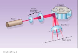
Laser scanners transform information moving between the digital realm and the physical world. An optical scanning system can be an input scanner, an output scanner, or a combination of the two. The input device samples the information space in a predetermined pattern, deriving a stream of data elements of various intensities that represent the original information, making it available for electronic manipulation (see Fig. 2).The output device assembles a series of data elements in a predetermined pattern, with intensity information taking on a binary or more-complex form. The data are output one pixel at a time along the fast-scan axis with a galvanometer or translation device indexing the image in the slow-scan axis.
For any given application, there is a group of scanning devices from which to choose. These include polygonal scanners, acousto-optic beam deflectors, galvanometric scanners, holographic scanners, and piezo deflectors. In addition to these scanning components, there are other imaging technologies that compete with scanners, including diode-laser arrays, charge-coupled-device (CCD) arrays, digital micromirrors, and ink jet devices.
The advantage of polygonal scanners compared to other scanning devices is speed, says Glenn Stutz, executive vice president of Lincoln Laser Co. (Phoenix, AZ). Galvanometers are limited to a few hundred hertz with reasonably sized apertures and incorporate a nonlinear sweep at these speeds. Acousto-optic scanners are limited in scan angle and number of resolvable points. Holographic scanners are the only devices that can compete with polygonal scanners at high speeds, though no one has found a way to package such systems cost effectively, says Stutz.
A polygonal scanner is a rotating metal disk with facets cut into the edges. The disk rotates on ball- or air-bearing spindles driven by hysteresis synchronous or brushless dc motors. The scanner provides a repetitive, uni directional scan that is superimposed in the scan field or plane.
The facets, or individual mirrored faces cut into the aluminum disk, vary in number, shape, and size. "We have some `standard` mirror sizes, but the optics community prefers to design a custom mirror for each application," says Stutz. The number of facets ranges from 1 to 72 with sizes ranging from 2 × 2 mm to several inches one side.
In the world of polygonal mirror scanners, there are four basic assemblies. A regular polygonal scanner has plane mirror surfaces parallel to and facing away from a rotational axis, uniformly distant from the rotational axis and located with equal polar coordinates (see Fig. 3).1 The major applications for this scanner are nonimpact computer output printers, laser inspection systems, infrared viewing systems, and graphics facsimile systems.An irregular polygon has a number of facets at a variety of angles with respect to the rotation axis. The mirrors face away from the axis. The polar locations may be irregular as well, with a lot of angles, or regular (equiangular). The significant technical feature of irregular polygons is that they produce non-superimposing repetitive scans.
They are commonly used for point-of-sale scanners for reading universal product code (UPC) symbols. In the barcode scanner, an irregular polygonal mirror deflects a laser beam over the barcode pattern. Backscattered light of differing intensities between bars and spaces provides the scanner with the information needed to digitize the barcode. Irregular polygon mirrors are also used for multiple-detector infrared scanners, laser heat-treating systems, and intrusion-alarm scanning systems.
The third scanner assembly, the pyramidal polygon, has its facets at an angle, rather than parallel, to the rotational axis. In the most-common variety, the facet angle is 45° to the spin axis. These scanners are primarily used for package sorting in barcode scanning applications.
A less common type of scanner is the inverted polygon. In this device, the facets are parallel to and facing toward a rotational axis. Military applications such as missile guidance and reconnaissance are among the few uses for inverted polygons.
Cost drives advances
Competition, customers, and technological advances are becoming more demanding, more critical, says Lincoln Laser vice president of sales Robert Nehrbas. "They are constantly pushing us to get parameters that we never bothered with before."
Balance and vibration are examples. "If you put your hand on the top of a scanner, you wouldn`t be able to tell that it was moving," says Nehrbas. But once that scanner is placed in a sensitive device, aberrations caused by vibrations from the device are detected. Higher-resolution applications have tighter pixel-placement requirements. "This forces us to tighten parameters such as cross-scan error, jitter, and velocity stability," says Nehrbas. This drives improvements in mirror manufacturing, motor design, and motor control design. Acoustical noise is now a major issue as scanner speeds increase. "The constant march toward high performance while at the same time reducing cost is the challenge we will continue to face," says Nehrbas.
"The world is moving toward smaller and smaller components," says Glenn Stutz. "In today`s market, size is cost. Our motivation is to keep reducing cost, primarily by reducing size. This is not only to beat the Japanese competition, but to keep laser scanning as the technology of choice for printers. Texas Instruments (Dallas, TX) is developing micromirrors (see Laser Focus World, Aug. 1997, p. S5), and other companies are developing light bars to replace the laser scanners. The only way to keep ours the technology of choice is to keep costs down to ward off competition. We`ve been around for a good 20, 30 years now. They forecasted the death of polygonal scanners about 10 years ago . . . but as long as we continue to advance, we will see another 10 to 15 years at least," predicts Stutz.
ACKNOWLEDGMENTS
The author wishes to thank Glenn Stutz and Robert Nehrbas of Lincoln Laser Co. (Phoenix, AZ) for their help with this article.
REFERENCE
1. Gerald F. Marshall, Optical Scanning, Marcel Dekker Inc. (1991), p. 351.
Smaller scanners lead the way
An air-bearing polygonal scanner under development at Lincoln Laser Co. (Phoenix, AZ) is paving the way for the next generation of smaller, faster, and less-expensive laser printers (see photo). This 1 × 2 × 4-in. device, which has a maximum rotation speed of 32,000 rpm (conventional polygonal scanners rotate from 15,000 to 18,000 rpm) has been specifically designed for laser applications such as Xerox`s family of digital office products.When one of the company`s customers asked for a miniature scanner at a particular price, engineers were sent to the drawing board. Individual subsystems, such as the air bearings, motor, polygonal mirror, and controller, were closely analyzed for better design cost efficiency. "This proved to be more difficult than we imagined, so we had to open each subsystem up," says Lincoln Laser`s Glenn Stutz. "We looked at inner rotor vs. outer rotor designs and Hall-effect controllers vs. back EMF controllers." Back EMF control eliminates the need for Hall-effect devices, reducing part count and complexity. Researchers built a prototype device and developed both detached and integrated motor controls. They analyzed different manufacturing methods. "This was an education," says Stutz. "We invited vendors into the problem and asked for their input."
A preliminary bill of materials was generated at the start of the project and a target cost assigned to each subsystem. These targets were monitored throughout the design process, and each design was analyzed for performance and cost.
The resulting polygonal scanner incorporates new controller technology, new motor designs, and new air bearings. It is 1/4 the size of other standard motor polygon assemblies, with a speed range from 16,000 to 32,000 rpm, speed stability of <0.015% over 1000 revolutions, and low jitter. Its performance will match, and in some cases exceed, that of the existing product line while having smaller size and lower costs, says Stutz.
The cost for large-volume purchases—the driving factor in the whole project—is expected to range from $45 to $55 per scanner, complete with driver card. This is significantly less than a conventional air-bearing model at $110/scanner without a driver card, says Lincoln Laser`s Robert Nehrbas. Prototypes of the MPC-32 will be available in the fourth quarter of this calendar year. A marketable product should be out by the middle of next year.
About the Author
Laurie Ann Peach
Assistant Editor, Technology
Laurie Ann Peach was Assistant Editor, Technology at Laser Focus World.


