While the most important application of optoelectronics is the transmission of information by optical fibers, fiberoptic devices linked to electronics are also in widespread use as the producers of information—as fiberoptic sensors. Such sensors have shown significant advantages over conventional predecessors—they are cheaper, smaller, resistant to electromagnetic interference, more reliable, and, in many cases, more accurate. Increasingly, fiberoptic sensors are being integrated in structures ranging from aircraft to bridges, making possible the continuous monitoring of the strength and integrity of such structures.
Over the years, fiberoptic-sensor technology and telecommunications technology have complemented and reinforced each other. Many of the components used in telecommunications were first developed for fiberoptic sensors, and the mass production inherent in telecommunications has driven down component costs, making new sensor applications practical.
Two types of sensors
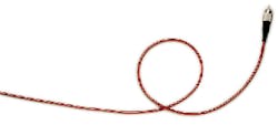
Broadly speaking, all fiberoptic sensors fall into two categories: intrinsic sensors, in which changes in the environment directly alter the properties of the fiber, and extrinsic or hybrid sensors, in which some transducer—an external device—converts an environmental change into a change in the light-trans mission properties of the fiber. A simple example of an intrinsic sensor is one that senses distortion through the bending of a fiber. As the fiber bends, light begins to leak out, dropping the transmitted intensity at the detector. A simple hybrid sensor consists of a fiber and a reflective end cavity that deforms in response to an environmental change, such as pressure, in turn changing the response of a multimedia fiber.
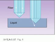
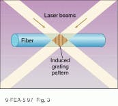
Many intrinsic sensors utilize total internal reflection. In a typical arrangement, a fiber is terminated with an angled end. If the refractive index of the surrounding medium is much lower than glass, all the light will be reflected back down that fiber to a detector. If, however, the refractive index changes, light can leak out, cutting the detected intensity. Such a simple device can be used, for example, to detect the level of a liquid or for low-resolution measurements of pressure in a liquid (see Fig. 1).Such Bragg gratings were first used for strain measurements with typical wavelength change of 1 nm for a strain of one part in a thousand (one millistrain). Generally, wavelength resolutions of about 0.01 nm are required, and, at this level, sensors can react as well to temperature or pressure changes. To achieve such resolution, a number of wavelength-demodulation techniques are used that involve either tunable filters or interferometers.
Tunable filters can be Fabry-Perot types, but a more sophisticated approach uses tunable acousto-optical (A-O) filters (see Laser Focus World, Nov. 1995, p. 93). These have photoelastic materials, in which the refractive index changes with the mechanical strain in the medium. A piezoelectric transducer bonded to such an A-O material transforms electrical signals into mechanical strains. The strains in turn set up waves of refractive-index change. Light passing through the waves of refractive change produced by the acoustic drive are diffracted. Because the diffraction depends on both the frequency of light and frequency of the imposed RF acoustic waves, A-O cells can be made to act as tunable frequency filters. As the resonant frequency is scanned across a wavelength range, a highly resolved transmission spectrum can be read out, with the dip caused by the Bragg grating located accurately.
In the interferometric approach, the signal is sent to an unbalanced Mach-Zehnder interferometer—one with two arms of unequal path lengths. As the transmitted spectrum shifts slightly in response to changes in the Bragg grating, there is a shift in the phase output of the interferometer. The phase modulation can be moved into the RF by modulating the source. In these interferometers, wavelength shifts of 10-6 nm can be detected, enough to detect strains of one part in a billion.
Interferometers yield precision
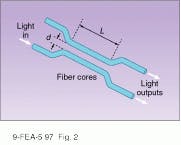
The approach that provides the most sensitivity in many applications is making the fiber sensor itself into an interferometer, with Sagnac, Mach-Zehnder, and Michelson interferometers being the most important types. In Sagnac interferometers, loops of fiber have interference between counter-rotating beams, in Mach-Zehnder interferometers, beams travel along two parallel fibers, and in Michelson interferometers, mirrors return beams from two legs, usually at right angles, back to near the interference source.
By far the most widespread use of Sagnac interferometers is in fiberoptic gyroscopes (gyros), now almost universally used for internal navigation systems in aircraft, spacecraft, missiles, and even automobiles. The basic idea of a fiber gyro is that when the fiber loop rotates, it takes a light beam slightly longer to go around the loop in the direction that it is rotating than in the opposite direction, because in the interim the end of the loop has moved. (Such fiber gyroscopes are good illustrations of the absolute character of rotation in contrast to the relative nature of translational motion.)
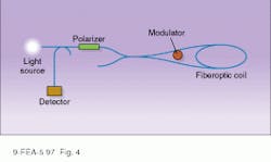
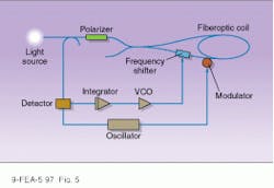
In the simplest type of fiber gyroscope, the open-loop gyro, light from a source such as an LED is passed through a polarizer and then split with one beam passing through a time-varying phase modulator (see Fig. 4). The two beams counterpropagate around the loop and are combined at an output detector. Because rotation creates a difference in path length, the two signals become out of phase; the faster the rotation, the greater the phase difference. This leads to a interference signal at the output that grows with increasing rotation. However, this approach is limited, because eventually the two signals are 180° out of phase, and the phase difference decreases with increasing rotation rate.Extrinsic interferometers
Mach-Zehnder and Michelson interferometers are characteristically used as part of hybrid or extrinsic sensors, with a transducer creating an environmentally sensitive change in one optical path. A common approach is to bond the fiber to a coating that stretches or contracts in response to acoustic, electric, or magnet fields. For example, a fiberoptic seismometer consists of a mass mounted on a soft rubber mandrill attached to two fiber coils, one above the other below the mass. Slight vibrations in the mass are amplified by making each fiber one arm of a Michelson interferometer.
Extrinsic or hybrid fiberoptic sensors can be based on a wider variety of phenomena than intrinsic ones, and in many cases fiber is basically used only to transmit the light from the transducers. In the case of fluorescence-based fiber, commonly used for medical and chemical sensing, fluorescent material is embedded in the tip or along the edges of the fiber. Light is propagated down the fiber, and the fluorescence signal is conveyed back to the sensors near the source. Changes in fluorescence can measure such parameters as viscosity and water-vapor content, or the presence or absence of certain chemicals. Where fluorescent materials are spaced along the exterior of the fiber, a light pulse is sent down the fiber and the various florescent responses are distinguished by the time of their arrival back at the detector.
Distributed multipoint sensing
One of the great advantages of fiberoptic sensors is that they can act as distributed sensors, recording a parameter over the entire length of the fiber. To do this, some scheme must be designed to extract the data from different sensing units along the fiber. Time-division multiplexing, the scheme just described, is one of the most common. However, wavelength-division multiplexing is becoming more popular. Here, interferometric or grating units can be tuned to different wavelengths and interrogated by a source with multiple wavelengths. A variation on this theme is to drive the wavelength or frequency of the source repeatedly over a range, interrogating, in turn, sensors tuned to different frequencies, a technique called frequency-division multiplexing—a somewhat arbitrary term because wavelength and frequency multiplexing are, strictly speaking, synonymous.
One of the more exciting applications of such distributed sensors is in smart structures, where fibers are attached to or embedded in a structure during construction with sensors to detect stress. In use, the sensor system is interrogated repeatedly by a controller microprocessor and light source, with the data fed back into the processor for analysis. In this way, early warning can be given if any part of the structure is in need of replacement long before it actually fails. Such smart structures would be particularly useful in the case of railway switches and bridges, whose failure continues to cause rail accidents. Such applications are not yet a widespread reality but, with rapidly dropping costs for fiberoptic sensors, rail safety applications could soon increase.
ACKNOWLEDGMENT
Thanks to Eric Udd of Blue Road Research (Troutdale, OR) for permission to reproduce the figures.
FURTHER READING
E. Udd, Rev. Sci. Instrum. 66, 4015 (Aug. 1995).
G. Meltz, SPIE 2838, 2 (June 1996).
About the Author
Eric J. Lerner
Contributing Editor, Laser Focus World
Eric J. Lerner is a contributing editor for Laser Focus World.
