Single-chip ROADMs are produced the 'fabless' way
Optical devices based on a multifunctional optical processor are combined to form monolithic single-chip reconfigurable optical add/drop modules. The devices are fabricated using silicon oxynitride–based waveguides and sub-0.25-µm lithography in a fabless approach.
In the field of dense wavelength-division multiplexing (DWDM), the reconfigurable optical add/drop module (ROADM) is headed for wider use. At Clarendon Photonics, monolithic fabrication methods have led to the commercialization of a four-wavelength ROADM that includes a variable optical attenuator (VOA) and an eight-wavelength version with no VOA.
These integrated-optics devices are manufactured in a "fabless" approach, in which we do not require a fabrication facility ("fab") on the premises of our manufacturing site. This approach has allowed us to produce the first monolithic four-channel ROADM, the first monolithic ROADM with on-chip VOAs, and the first monolithic ROADM with an on-chip 4 × 4 optical-switch matrix.
An optical building-block approach
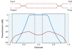
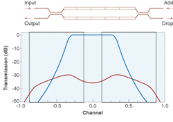
The central element of these devices is the dense, multifunctional and reconfigurable optical processor, dubbed the DMR (see Fig. 1). The DMR comprises identical 50% couplers at the input and output of two identical grating/resonator chains. During operation, DWDM signals enter the input port and are equally split by a 50% coupler into the two arms of the filter. The gratings reflect all but one ITU channel back into the coupler. The reflected light transmitted back through the input coupler experiences what is equivalent to propagation through a 100% coupler; as a result, all of the light reflected is transferred into the output port. Light that is transmitted through the grating resonators recombines through the 50% coupler at the add/drop side of the DMR. Again, light propagating through the gratings experiences an equivalent, cumulative 100% coupling and completely transfers to the drop port. Signals entering through the add port are processed in an identical manner with only one ITU channel reaching the output port.
The filtering capability of the DMR is a result of phase-shift resonators in the grating arms. The resonators each contribute a single pole to the filter response. Controlling the number of poles and the optical coupling between the poles allows designs of optimal filter responses. The frequency response of the DMR is characteristic of a Chebyshev Type II filter design. The response is very flat in the clear window at the center of the ITU channel, with ripple well below 0.1 dB. In addition, the width of the filter at the 0.5-dB point is considerably wider than the ITU clear window. With a typical 0.5-dB passband width of greater than 50% of the ITU channel spacing, the filter provides extra tolerance for signals that are not exactly centered on the ITU grid. The filter response also provides steep roll-off outside the passband with both adjacent channel and nonadjacent channel isolation performance well below 50 dB.
Dynamic operation from the DMR is achieved by using on-chip resistive heaters to modify the behavior of the filters. By imposing temperature gradients across the grating/resonator structures, the passband of the filter is changed from one that rejects all but one ITU channel to one that rejects all ITU channels.
Chip topology and resulting performance
In electronic integrated circuit–based products, the transistor is the basic circuit building block from which higher-level system functions are constructed. The earliest products, such as simple digital logic gates, contained only a few transistors per chip. As the technology matured, however, it was possible to put more and more transistors on a chip. Also, the earliest products were either 100% digital (logic, memory, or microprocessors) or analog (amplifiers, voltage references, comparators). Later, mixed-signal chips, featuring portions operating in digital mode and portions operating in analog mode, permitted the development of compact, low-cost, and sophisticated products, such as mobile telephones and MP-3 players.
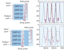
In comparing integrated optics and integrated circuits, there are strong analogies between the DMR and the transistor. Because it supports both digital and analog operation, the DMR makes a wide variety of optical system-level functions possible (see Fig. 2). For example, in a four-port, single-chip ROADM, four DMRs can be connected in a circuit that provides the capability to add or drop four ITU channels from signals present on the input-output path. In this case, the circuit behaves as an OADM that is dynamically configured via the on-chip microheaters.
FIGURE 2. A four-port, single-chip ROADM contains four DMRs connected such that they can add or drop four ITU channels from signals present on the input-output path (top left). The actual performance of such a product is illustrated (top right). Four additional DMRs can be included in the path of the add port signals to allow independent control of the signal level of each add signal (bottom left). Data from a commercial product based on such a chip demonstrate how each of the chip's on-board VOAs can independently control the signal level of the four add port signals (bottom right).
Through the use of additional DMRs, it is possible to include additional functionality on the chip. In this case, four additional DMRs are included in the path of add port signals. These devices are operated in linear mode and enable the signal level of each add signal to be independently controlled. This mix of digital and analog optical capabilities enables stand-alone ROADMs and discrete VOAs to be replaced by a single monolithic waveguide chip.
Other types of system functionality already demonstrated with the use of DMRs include sophisticated M × N optical-switch fabrics, two- and three-port tunable filters, and frequency-selective monitoring ports.
Scaling up
Service providers need optical-networking solutions that eliminate the extensive network-planning exercises associated with current low-channel-count, fixed OADMs. To satisfy these end users, system manufacturers are looking for dynamic solutions with the ability to access any ITU channel. Highly flexible, low-cost, dynamic solutions are necessary to enable next-generation optical networks.
While our integrated-optics-based ROADM devices address the needs for dynamic configurability and low cost, they do not yet address the need for higher channel counts and wider flexibility. It is clear that meeting these needs will require chip designs incorporating larger numbers of DMRs. Up from today's waveguide chips with 4 to 12 DMRs on a 49-mm2 chip, next-generation products will provide system-on-a-chip functionality and will pack 40 or more DMRs on a 144-mm2 chip.
The fabless model
Achieving reliable, low-cost production is necessary for the long-term success of a manufacturer of optical integrated circuits. Rather than spend millions of dollars staffing and running an in-house fab, we opted to pursue a fabless semiconductor model. This presented us with several interesting challenges.
First, an appropriate material system had to be selected for our platform. Integrated optics has always been associated with either conventional materials—for example, silicon or SiO2 (silicon dioxide)—or more-exotic III-V materials such as lithium niobate, indium phosphide, and gallium arsenide. In the case of the III-Vs, we determined that few vendors could provide a process that was mature enough to ensure a stable source of wafers economical enough to meet our cost targets and flexible enough to accommodate our requirements.
At first glance, a CMOS-based fabless strategy provides a wide range of materials to choose from. However, because gratings play such an important role in the performance of the DMR, this factor heavily influenced our eventual choice of fabrication process.
In integrated optics, the use of gratings is widespread and well understood. Two key parameters of particular interest for the production of gratings are grating pitch and effective index of refraction. Controlling these two parameters is a challenge because of their strong dependence on materials and lithography.
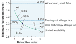
The pitch (or feature size) and index of refraction associated with the production of grating-based devices in a CMOS fabrication line have a typical relationship that transforms the choice of materials (see Fig. 3). Armed with this knowledge, the choice of materials and lithography became a practical matter. Though widely available, 0.5-µm lithography simply was not an option for the production of gratings in a CMOS environment because of the lack of a native material with suitable index. At the other end of the spectrum, the limited availability of 0.1-µm lithography precluded, at least for now, a choice of silicon for waveguide material.
Within the available range of between 0.25 and 0.13 µm, factors such as chip size (minimum bend radius), grating strength, and layer thicknesses drove our decisions. The wafers are produced in a 200-mm CMOS DRAM (dynamic random-access memory) line using silicon oxynitride–based waveguides and sub-0.25-µm lithography.
Packaging
The final challenge presented by the choice of a fabless semiconductor strategy involves packaging. It is widely known that packaging costs remain a significant element of finished-product costs for integrated-optics products. We have elected to use the industry-standard pin-grid arrays that are typically used to assemble microprocessor chips, digital signal processors, field-programmable gate arrays, and other high-density integrated circuits. This decision was driven by our need for high pin counts suitable for system-level functions, sufficient area for fiber pigtailing, access for heat-sinking, and costs that have already been driven down to the tens of dollars. Standard die-attach, wire-bonding, V-groove arrays, and fiber-ribbon strain relief complete the assembly flow of the integrated-optics products.
At the time of writing, JIM FORESI was vice president of engineering and BILL THOMPSON was vice president of marketing and business development for Clarendon Photonics, 153 Needham Street, Newton, MA 02464; e-mail: [email protected].


