Lightpipe and integrating box provide uniform irradiance
Many electro-optical devices have components designed to achieve uniform illumination over a defined angular range. Examples include liquid-crystal displays in consumer electronics products—such as cellular phones and palm pilots—automotive dashboard lighting, and the backlit ring around some automobile ignitions. Good uniformity can be achieved using electroluminescence (EL) or a number of discrete LEDs (organic or inorganic), but the price of the electro-optical components makes these designs cost prohibitive for the high volumes in which consumer electronics devices and automobiles are produced.
Injection-molded plastic lightpipes coupled with LEDs or incandescent sources are relatively cheap to manufacture, making this design the most common choice for achieving luminance uniformity. Light is collected from the source and then propagated along the lightpipe by means of total internal reflection. Uniformity is achieved by ejecting this "trapped" light at locations along the length of the lightpipe. A common method to do this is to place a pattern of white dots or dimples on the bottom surface of the lightpipe—often called scatter sites. These geometrical obscurations frustrate the total internal reflection and cause light to escape.
Optical-analysis software, such as Breault Research Organization's Advanced Systems Analysis Program (ASAP), can be used to develop an optimized pattern of scatter sites and illumination uniformity. In addition to familiarity with optical-design software, an optical engineer building a lightpipe with scatter sites must also have a working knowledge of a computer-aided design (CAD) program, have extensive design experience, and be ready to perform multiple design iterations.
An understanding of the manufacturing limitations of injection-molding processes is also required. Shapes such as hemispheres have draft angles that make them impractical, or impossible, to manufacture via injection- molding techniques. Knowledge of mechanical engineering and manufacturing details and a design approach that forces the optical engineer into a game of trial and error make lightpipes with scatter sites complicated, time-consuming design projects.
Another method to achieve uniformity is to use an integrating-box approach. In this case, light is injected into an enclosed, diffuse, white structure behind the display. Light scatters from the white surfaces until it is emitted from the display surface. The benefit of this approach is that the integration of the light makes it easy to achieve uniformity over localized areas. Another attractive feature of this method is the low cost of the parts—integrating box designs do not require optical-grade surface quality. In fact, optical-grade quality often detracts from performance. The downfall of this approach is that when used alone, integrating-box designs suffer from "hot spots" near the source of the illumination system.
Combining the injection-molded lightpipe with an integrating-box design results in a system that performs well, maintains the cost of a lightpipe design, and is relatively easy to design because no lightpipe scatter sites are required. In this application the lightpipe only transports light throughout the integrating box.
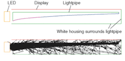
In a combination lightpipe and integrating-box design, the display can be represented by a surface covering the top of the system (see Fig. 1). In reality, this can consist of a plastic cover with a thin layer of translucent paint, or a liquid-crystal display with a translucent mylar film beneath it. A white plastic housing surrounds the lightpipe. Light from the source (in this case, a single LED) is collected at the inlet shown on the left. The lightpipe transports the light throughout the housing. The wedged shape allows light to escape as it travels toward the right end. The cross-sectional area of the lightpipe decreases with increasing distance from the source input to frustrate total internal reflection along the length of the lightpipe. Some of the escaping light directly hits the display. However, most of the light is scattered from the walls of the housing. This light scatters off the diffuse, white walls, which greatly assists in providing luminance uniformity at the display.
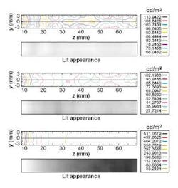
With few iterations of manually optimizing the shape of the lightpipe, the combination design is able to achieve reasonable uniformity at the display (see Fig. 2). The peak value is 1.7 times brighter than the minimum value (uniformity is ±25%). Further optimization of the combination system can result in uniformity on the order of ±10%. With only the lightpipe, the peak value is almost four times greater than the minimum value. As shown by the lit appearance, the nonuniformity is apparent. With rigorous optimization, the uniformity can be improved to approach the uniformity of combination system design. However, the effort required is at least an order of magnitude greater. Even worse, the integrating box alone results in a peak value that is 17 times greater then the minimum value. Little can be done to improve the stand-alone integrating-box design.
Another benefit of the combination system is that it is not highly sensitive to the tolerance error associated with injection-molded parts. The free-form wedge shape of the lightpipe changes little as it is polished, and the walls of the white integrating box have loose tolerances because light is only scattering off these surfaces.
The combined lightpipe and integrating method is efficient, easier to design, cost-effective, and results in a product that will not suffer from stringent tolerance requirements.
MARK KAMINSKI is an optical engineer at the Breault Research Organization, 6400 East Grant Road, Suite 350, Tucson, AZ 85715; e-mail: [email protected].


