Planar waveguides offer route to integration
Optical integration is an attractive way to improve network performance with reduced size and costs, but its goals have shifted from systems to modules and subsystems, with a major emphasis on reconfigurable optical circuits.
The idea of integrated optics had a compelling logic when Stewart Miller of Bell Labs proposed it as an optical analog of integrated electronic circuits in 1969. Today optical integration remains an attractive way to improve performance while reducing size and costs, but its goals have shifted from complete systems to modules and subsystems, with a major emphasis on reconfigurable optical circuits based on planar waveguides.
The early goal of integrating all optical and electro-optic functions into a single device proved elusive. No single material system works well for the broad range of network elements from transmitters and receivers to switches and variable attenuators. Perhaps more important, network architectures have also changed. Functions are now distributed among modules and subsystems, so integration has become more important on that level. Networks also want flexibility, so integrated modules must be reconfigurable.
These trends have made reconfigurable planar waveguides a key part of the new realm of integrated optics. The main concept is to integrate an array of active and passive planar waveguide components that can reconfigure the network as needed. The active components include switches, modulators, and variable optical attenuators. They are aided by passive waveguide components that split or combine signals in other ways, including couplers and arrayed waveguides, which multiplex and demultiplex optical channels.
Basic concepts and building blocks
Planar waveguides are thin stripes of high-index material formed on a flat substrate of lower refractive index. The high-index stripe is surrounded by lower-index materials, which confine the light in the high-index waveguide as the cladding confines light in the high-index core of an optical fiber. The waveguide can be a raised layer of high-index material deposited on top of a flat substrate, partly surrounded by air. Another approach is to form the waveguide by implanting a dopant that increases the refractive index of the substrate. Photolithographic techniques also can deposit the waveguide stripe within a stack of lower-index layers that surround it completely.
Waveguide devices are integrated by placing them in sequence on a substrate. They fall into three basic classes: simple waveguides that merely transmit light from point to point, like conductors in integrated electronics; passive or static devices, which operate on the optical signal in some way, but always perform the same operation. Examples include arrayed waveguides and couplers, which always divide input signals in the same fashion, and active or dynamic devices that can change the operation they perform on the optical signal. One example is a switch that can direct input signals to one of two possible outputs. Another is a modulator that can be adjusted to transmit different fractions of the input light. Changing the operations performed by active or dynamic devices reconfigures the entire optical circuit. These changes also can affect the operations performed by passive devices by changing what signals reach them.
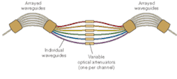
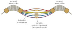
The arrayed waveguide (AWG) is the most important of the passive waveguide elements used in reconfigurable devices. Arrayed waveguides can be used as demultiplexers or multiplexers. In many reconfigurable circuits, they are used in pairs (see Fig. 1). Input signals enter a demultiplexing AWG that breaks the signal into its component optical channels and delivers each wavelength to a separate output waveguide. The output waveguides can deliver each channel to a separate switch or modulator that operates on that wavelength independently. Then the second AWG multiplexes together the modified signals, which continue to their destinations.
Waveguide switches are Mach-Zehnder interferometers, which divide the input signal between a pair of parallel arms, then recombine the signals emerging from the two arms in a 2 × 2 coupler. Changing the refractive index of one or both of the arms shifts the relative phases of the two beams, which recombine at the 2 × 2 coupler, causing interference that changes the fraction of the light emerging from the two output ports of the planar coupler. The refractive index can be changed in different ways. The thermo-optic effect changes the relative temperatures of the two arms by applying heat through metal heaters on the surface above the waveguides; it works for all materials. The electro-optic effect applies different voltages across the two waveguide arms to shift their refractive indexes, but works only in a nonlinear material like lithium niobate.
The same Mach-Zehnder interferometer effect also can be used to modulate the light intensity emerging from one of the coupler output ports. In this case, the drive signal modulates the output intensity over a continuous range. Similar devices used as switches are driven between fixed bias levels that switch the signal between a pair of ports. The thermo-optic effect can modulate intensity on millisecond scales, fast enough for some reconfigurable optical circuits and variable optical attenuators. Electro-optic modulation can switch signals in tens of picoseconds, fast enough for modulation at high data rates. Electro-absorption modulation is possible in waveguides fabricated in the junction layers or semiconductors; it also has speeds of tens of picoseconds.
Applications forreconfigurable circuits
Switching reconfigures the path of light passing through a network of waveguides for a variety of applications. Two main uses are in optical cross-connects and reconfigurable optical add/drop multiplexers.
A crossconnect can transfer signals from any of N input ports to any of M output ports; optical crossconnects are implemented with optical switches. In theory, N and M can be arbitrary numbers and during "the Bubble" developers tried to build huge optical cross-connects with thousands of input and output ports. However, that market never materialized and the MEMS (microelectromechanical systems) switches they used proved hard to implement. Today interest in optical crossconnects is focused on much lower port counts, such as 8 × 8.
Waveguide switches are implemented by cascading a series of individual switching elements, so they are much more compatible with low port counts than with giant crossconnects. A 1 × 8 can be implemented by cascading a number of 1 × 2 switches that can switch one input signal in two different directions (see Fig. 2). Each stage in the cascade can direct the input signal in one of two directions, doubling the number of possible outputs.
Each waveguide switch has two input ports, so N × M switches can be assembled from more complex cascades of 2 × 2 switches. Waveguides may cross in the switching cascade. Small thermo-optic switches are about the size of a small cell phone; ones with total port counts up to 40 can fit into a package 6 × 5.5 × 0.4 inches, including heat sinks. Larger switches can be assembled by building up smaller modules.
Reconfigurable optical add/drops are also well matched to the capabilities of waveguide switching. In the design shown in Fig. 3, the input is a number of optical channels carried on a single fiber, demultiplexed by passing through an AWG. The illustration shows only four wavelengths to simplify the drawing but the design can handle more channels. Input channels are either passed through to the output port or diverted to a local drop point.
Mach-Zehnder interferometers are really modulators, so waveguide add/drops do not have to be pure off/on switches. They also can divide signals between the pair of outputs in various ratios, depending on system requirements. This makes it possible for the switch to drop the entire signal, divide it between local and output ports, or split off a small portion for local monitoring.
The modulation capability of Mach-Zehnders also can be used in variable optical attenuators that also functionally reconfigure the system in some way. A separate variable optical attenuator, for example, can be used on each channel between the two AWGs in Fig. 1 to fully transmit, attenuate, or block the signal.
Network operators may require different levels of reconfigurability. If changes are infrequent, they may be satisfied with an optical add/drop that must be changed by sending a technician to the site. If changes are more likely, they typically prefer remote reconfigurability, in which changes can be made from a central office. Operating requirements of remote switches depend on the applications. Protection switching redirects signals when faults are found on the network. Typically they switch all signals on a fiber to a different route, providing quick recovery from a broken cable. Provisioning changes network configuration, usually when services being provided change. Both can be performed on time scales of milliseconds or longer.
Materials and hybrid devices
Electro-optic waveguide switches must be made of nonlinear materials in which the refractive index varies with the applied voltage; the usual choice is lithium niobate. Electro-optic Mach-Zehnders respond quickly enough to serve as high-speed modulators, but this fast response generally is not needed in reconfigurable waveguide circuits. Other materials are used in other waveguide devices, including thermo-optic switches.
Silica (silicon dioxide) on a silicon substrate is widely used for AWGs and thermo-optic devices. The material is inexpensive and waveguides can be fabricated photolithographically. The refractive index of silica matches that of fiber cores, easing coupling requirements. Heat can be applied by metal elements deposited over the waveguides. The devices are rugged; Lynx Photonics (Calabasas Hills, CA) reports operating temperatures range of -90°C to +140°C and demonstrated one circuit on a shaker table at OFC 2004 in Los Angeles.
An alternative is fabrication of silicon waveguides on an insulator, which typically is silica on a silicon substrate. The high refractive index of silicon allows tighter bends—an important consideration because planar waveguide devices require large areas relative to electronic devices. However, coupling into the high-index silicon can be an issue.
Planar waveguides also can be fabricated in III-V semiconductors, which have attracted particular interest for transmitter and receiver integration because light sources, optical amplifiers, and detectors can be integrated with waveguides. Their high index also allows compact devices but the materials are quite expensive and indium phosphide substrates are limited in size.
The wide differences in material properties have led some developers to turn to hybrid integration to optimize performance of all components. At OFC, Toshikazu Hashimoto and colleagues of the NTT Photonics Laboratory (Atsugi-Shi, Japan) described hybrid integration of light sources and detectors with silica-on-silicon waveguide circuits. They used surface mounting in a bidirectional 1.25-Gbit/s optical transceiver for a fiber to the home at 1.31 and 1.55 µm, and facet mounting for an eight-channel CWDM receiver.
Outlook
The central appeal of integrated optics remains similar to the original goal 35 years ago—developing inexpensive and mass-producible optical systems. Today's need is primarily for modular elements for applications in switching and terminal equipment. NTT already uses a 155-Mbit/s planar-waveguide transceiver in home fiber terminals and it hopes to deploy the 1.25-Gbit/s circuit after improving its performance and reducing its costs.
New technologies continue to emerge. Polymer planar waveguides look like a promising alternative to existing materials. They are inexpensive and can be made in large sizes but operating temperatures and device performance remain challenging goals. Other challenges remain, like integrating temperature-sensitive AWGs with thermo-optic components. Nobody expects integration to be easy, but it is coming.
ACKNOWLEDGEMENT
Thanks to Michael Leigh and Abe Queller of Lynx Photonic Networks.


