Hemiellipsoidal mirror increases accuracy of reflectometer
Hemiellipsoidal mirror increases accuracy of reflectometer
John T. Neu
Directional reflectance data are required in many applications, including defense, space exploration, observables control, tailored coatings de sign, quality control in manufacturing, and remote sensing for identification of materials. This information is generally acquired using Fourier-transform infrared (FT-IR) spectrometers mated to reflectance modules that incorporate diffuse gold integrating spheres. Although such units work well in certain applications, the spheres inherently suffer from very low radiant throughput; only about 0.5% of the source radiation illuminates the sample, seriously limiting system performance.
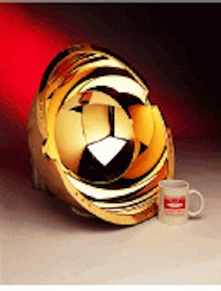
An alternative to the conventional integrating sphere is to use a hemiellipsoidal mirror to focus the source (see figure). A directional reflectometer developed by engineers at Surface Optics (San Diego, CA) incorporates a large, high-quality specularly reflecting hemiellipsoidal optic that focuses more than 90% of the infrared source energy on the sample. An associated hinged-mounting hardware mechanism maintains precise ellipsoid figure and positioning after sample mounting. The reflectometer was designed to operate with a 550 FT-IR spectrometer from Nicolet Instruments (Madison, WI).
The increased signal strength extends the measurement capability of the directional reflectometer, providing en hanced coverage of the conventional measurements and providing other data not generally available from standard systems, including thermal emittance data, optical constants, and polarized beam operation.
Hemispherical directional reflectance
Unlike conventional reflectometers, the SOC-100 operates in reciprocal mode: source and sample are placed at the foci of the ellipse, while the detector is installed outside of the integrating surface. Hemispherical directional re flectance (HDR), the data gathered in this reciprocal mode, is equivalent to directional hemispherical reflectance in which the source and detector positions are interchanged.
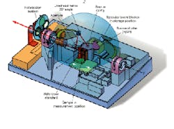
A large-aperture isotropic infrared source at one focus of the ellipse uniformly illuminates the hemiellipsoid, which in turn uniformly illuminates the sample at the other focus. The elliptical overhead mirror receives the reflected radiation from a 0.32-in.-diameter spot on the sample and focuses it on a 0.32-in.-diameter aperture in the ellipse plane. Outside of this aperture, a pair of optical flats directs the expanding beam to a 1.5-in.-diameter, 90° off-axis parabola that collimates the beam and relays it to the FT-IR spectrometer.
This optical train, including the overhead collection mirror, rotates around the ellipse minor axis through the sample face, allowing the overhead mirror to view the sample from directly above (0° beam angle) to directly below the sample position (180° beam angle). The system can thus record the HDR from 10° to 80° and measure scattered transmittance of semitransparent samples at angles from 0° to 40°. A stepper motor shifts a two-position shutter blade from `open` to `closed` position in sync with the moving mirror in the FT-IR spectrometer. The transition takes less than 30 ms; dwell time depends on the resolution selected for the FT-IR instrument.
The measurement position may be occupied by a reflectance sample, a reflectance standard, or a transmittance sample. Interchange between these options is controlled by an automated stage. The reflectometer incorporates a beam blocker that allows approximate partition of the directional reflectance into a scattered component and a specular lobe. The blocker can also be stored below the ellipsoid plane.
Measurement process
Proprietary software controls the system and acquires, processes, and stores HDR data. After mounting the samples and starting the system, the operator initializes the computer program with measurement parameters (wavelength range, polarization angle, and so on) and chooses measurement options (reflectance, transmittance). Specialized application software packages allow determination of emittance, optical constants n and k, segmented coating design, and thermal design analysis.
Once the operator starts the measurement process, the computer directs the data-acquisition tasks, operating the FT-IR instrument, sequencing the operation of five stepper motors in the reflectom eter, providing real-time graphical display during data recording, processing and compiling the data to provide display and hard copies of tabular and graphical results.
An important capability of the SOC-100 is the measurement of emittance. Both directional emittance as a function of angle (10° to 80°) and total hemispherical emittance can be evaluated as a function of wavelength or in-band. For samples that do not change physically or chemically with temperature, the system derives emittances from reflectance data measured at ambient temperature with computed emittance at the required temperature. Samples that do exhibit thermal variation are measured over the temperature range from ambient up to 500°C.
Provided the wavelength measurement band extends over a high percentage of the Planck radiation curve at the temperature of interest, this approach yields accurate results. For wavelength coverage to 12 µm offered by conventional systems, the approximate coverage of an integrating sphere measures only 41% of the Planck curve at room temperature. Measurement to 45 µm, obtainable with the reflectometer, covers 96% of the curve and largely eliminates the uncertainty in the emittance-value determination.
Applications
A number of applications require HDR as a function of parallel and perpendicularly polarized radiation. To obtain directional reflectance of an unpolarized beam as a function of wavelength, for example, requires the average reflectance of beams in both polarization states, because spectrometer systems do not respond equally to parallel and perpendicular polarized beams. The error is negligible to about 6.0 µm, but reaches 2.5% at 15 µm, rising to 8% at 25 µm. This can introduce significant uncertainty in low-temperature emittance calculations that require data at wavelengths longer than 25 µm.
Polarized HDR data also can be used to derive optical constants. Obtaining the optical constants of powdered, diffusely scattering materials with an infrared source is a nontrivial process. At these wavelengths the reflectance spectra show single and multiple scattering effects that mask the bulk optical properties of the material. Specialized algorithms used in conjunction with polarized HDR data remove these effects from the directional hemispherical reflectance spectrum. The technique requires additional data on the powder size distribution, but the approach still provides bulk optical constants without requiring a smooth optical surface generated by a heating and polishing process that would chemically alter the sample. n
In reciprocal hemispherical directional reflectometer with hemiellipsoidal mirror (photo), output from a source at one focus reflects off the mirror to converge onto sample at second focus (bottom left). In actual system (above), overhead mirror views scattered radiation at specified angular settings and directs it through the optical train to an external detector.
JOHN T. NEU is a scientist with Surface Optics Corp., 9929 Hibert St., Ste. C, San Diego, CA 92131.


