Scanned linear architecture improves laser projectors
Scanned linear architecture improves laser projectors
To reach commercial viability, laser-based projector systems must incorporate fast modulators to overcome speed and bandwidth constraints.
Robert W. Corrigan
Lasers are natural sources for image-projection systems. They are stable, monochromatic, available in a wide variety of wavelengths, power levels, and geometries, and operate with high optical efficiency. Diode-pumped solid-state and direct-diode lasers appear destined to become compact, affordable sources at production volumes.
Yet laser projectors have not moved out of the research laboratory into the marketplace in any significant way. The chief reason is that the severe modulation design constraints imposed by traditional display architectures do not harness the strengths of a laser. Laser suppliers planning to enter the display markets must look to new display architectures.
Display system designers have traditionally used one of two architectures to project an image onto a viewing plane, either a scanned beam or a two-dimensional panel. Each of these has advantages and disadvantages, but neither method is intrinsically suitable for commercially successful laser-display products.
Scanned-beam approach
Scanned-beam architecture creates a single bright pixel that is scanned in two dimensions--in the same manner as a cathode ray tube is scanned--to create an image (see Fig. 1). The inherent advantages of this architecture include the absence of pixel boundaries, the ability to synchronize the system to a wide range of video input signals, and the ability to easily reformat image aspect ratios.
The intrinsic architectural disadvantages include the necessity of very high bandwidth that must pass through a single video drive channel, very tight system timing requirements, and the waste of light as the beams must be turned off while lines are retraced. Bandwidth and timing control issues make it difficult to scale this architecture to high resolutions.
Most of the prototype laser projectors that have been reported use a scanned-beam architecture. A typical design is based on three video channels (for red, green, and blue), each consisting of a collimated laser beam passing through an acousto-optical modulator. These channels are combined to form a composite beam that is scanned across a remote screen using a rotating polygonal mirror. Tight fabrication tolerances of the polygonal mirror array and precise control of that polygon while spinning at tens of thousands of revolutions per second present formidable design challenges.
These systems require high-power diffraction-limited laser sources, multiple acousto-optical modulators--which can be both expensive and inefficient, especially when modulating high-intensity beams--and a complex servo system to control the rapidly rotating polygonal mirror. A laser projector with this architecture has not succeeded in the marketplace because this system is too complex and expensive to justify its performance.
Two-dimensional displays
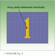
A two-dimensional panel associates one physical pixel on the modulator array with each addressable spot on the screen (see Fig. 2). Depending on the type of modulator, each pixel operates by altering either transmissivity or reflectivity. Examples of display technologies using two-dimensional panels include liquid-crystal display (LCD), digital micro-mirror (DMD), and liquid-crystal-on-silicon (LCOS).
The benefits of the two-dimensional architecture include sharp transitions between pixels, a display resolution limited only by the panel geometry, and low-bandwidth video channels because each pixel is updated only once per frame. The principal disadvantage of the two-dimensional panel architecture is the large number of pixels and video channels that must be fabricated within tight uniformity tolerances to achieve an acceptable image. Other disadvantages include a "screen door" (or fixed-pattern noise) effect around pixel boundaries and the complex electronics required to reformat an image between various aspect ratios.
A two-dimensional panel array needs to be uniformly illuminated over the relatively large area of the array. There is little advantage to using laser sources to achieve this illumination. Short-arc lamp sources are inexpensive and produce acceptable results. A laser projector incorporating this approach has not succeeded in the marketplace because the primary advantage of the laser source--very high brightness--is not translated into any performance advantage through the system architecture.
Combined approach
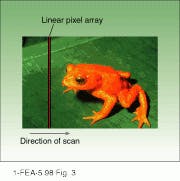
The scanned linear architecture combines the best features of the scanned-beam and the two-dimensional panel systems. The scanned linear architecture uses a linear array of physical pixels oriented along a vertical or horizontal column of image data (see Fig. 3). Once per image frame, this linear array is optically scanned across the screen to produce a complete image.
Unlike the scanned-beam architecture, the scanned linear architecture scans at the frame rate, rather than the line rate, a reduction of three orders of magnitude. The lower scan rate translates directly into less expensive and more reliable optical scanning.
A low-cost galvanometric scanner can be used in place of the costly and complex polygonal mirror. The video bandwidth per channel is also three orders of magnitude less than that of a scanned-beam system, simplifying electronic design. Like a scanned-beam system, the scanned linear architecture allows easy image reformatting to different aspect ratios (for example, between 16:9 and 4:3) and produces smoothly blended images without pixel boundaries.
The scanned linear architecture outperforms a two-dimensional panel architecture. The number of physical pixels in a scanned linear array is three orders of magnitude less than that of a two-dimensional panel array, which translates directly into higher manufacturing yields and lower modulator costs. The scanned linear architecture supports extremely high resolutions because the size of the array scales in a linear fashion rather than geometrically.
Most important, the scanned linear architecture leverages the strengths of a laser, while taking advantage of less-than-perfect laser sources. A Gaussian beam is formed into a line and directed onto a linear modulator by beam-shaping optics. Modulator geometry and illumination requirements for the linear array allow efficient coupling to diode-bar lasers and other multiple-emitter sources. Total system optical power does not have to be concentrated into a single diffraction-limited beam per color channel, enabling multiple laser beams to provide a range of on-screen brightness.
Design constraints
With these advantages, one might wonder why all display systems are not built using a scanned linear approach. The answer is that the scanned linear architecture imposes severe performance requirements on the modulator. Each pixel in the linear array must switch fast enough to render an entire row of pixels during each frame time. This requirement demands a switching speed three orders of magnitude faster than a comparable two-dimensional modulator.
To display a 1920 ¥ 1080-pixel high-definition TV image at a 100-Hz frame rate, for example, each pixel of a modulator having 1080 pixels must switch between gray-scale values at a rate of 4.2 µs (assuming 80% duty cycles to allow for blanking and retrace time). This rate is several orders of magnitude faster than the limits of typical LCD technologies.
Switching speeds are further taxed if the modulator is inherently digital. The DMD and certain LCOS technologies use pulse-width modulation techniques, requiring 10 or 12 switching cycles to create a single gray-scale value. This fact and their fundamental speed limitations mean that these technologies are approximately four orders of magnitude too slow to produce acceptable high-resolution images using a scanned linear architecture.
To support a scanned linear architecture, a modulator must also be robust enough to withstand the high optical energy required to produce a sufficiently bright display. In order to project a bright image onto a screen, a large light flux must be concentrated into a small area. The area of a linear array is perhaps three orders of magnitude smaller than that of a typical two-dimensional array. Therefore, projecting a bright image requires power densities in the range of mW/pixel, or kW/cm2, assuming a square pixel approximately 20 µm on a side. These power densities are beyond the range of most spatial light modulator technologies.
Grating light valves
Grating-light-valve (GLV) technology provides an alternative modulator design that supports both the switching speed--using either digital or analog means to achieve gray-scale--and the optical power density required to make a scanned linear display using low-cost lasers a commercial reality.
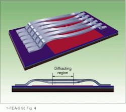
A GLV pixel is an addressable diffraction grating, formed of moving parts on the surface of a silicon chip. Each GLV pixel consists of dual-supported parallel ribbons formed of silicon nitride and coated with a reflective aluminum top layer (see Fig. 4). A pixel is turned fully "off" when all pixel ribbons form a flat reflective plane. A pixel is turned "on" by electrostatically deflecting alternate ribbons to produce a square-well diffraction grating.
Grating-light-valve pixels can be operated in digital mode--with alternate ribbon deflections either zero or l/4--or in analog mode--with alternate ribbon deflection to positions between zero and l/4. A Schlieren optical system is used to collect the modulated light from one or more diffraction lobes, while projection optics image this light onto a remote screen.
Grating-light-valve pixels switch very rapidly, having rise times in the range of 20 to 200 ns, three orders of magnitude faster than other reported technologies. The high pixel-switching speed--in both digital and analog modes--is due to the low mass of the silicon nitride ribbons, the small deflection distances (from 0 to l/4), and the high acceleration created by electrostatic forces.
Pixels based on GLV technology can handle power densities greater than 10 kW/cm2 primarily because of the pixel`s high effective reflectivity and durable silicon nitride composition. As there are no transistors near the optically active area of the array, there are no photo-induced leakage effects that could disturb electronic performance of the driver circuits.
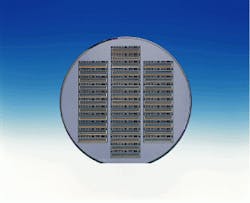
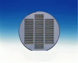
Most spatial light modulators have restricted acceptance angles, requiring incident light to arrive within a narrow symmetrical cone at each pixel for proper operation. The nature of the GLV technology`s diffraction allows for asymmetric acceptance angles, making effective use of a wider range of angles in one dimension. This attribute and the basic geometry of a linear array allow for efficient illumination coupling with a wide variety of emitter geometries, including low-cost diode laser bars. Many GLV devices can be created cost effectively by photolithographic techniques on a standard 6-in. silicon wafer (see photo on p. 169).
Linear GLV arrays and lasers are natural system partners in a range of cost-effective image projection applications. The fundamental speed and power density capabilities of the GLV pixel enable a unique system architecture, which takes advantage of the lasers` inherent strengths to produce high-performance, cost-effective display systems. With this architecture, laser-based color image projectors may be ready to move out of the laboratory and into the marketplace. o
Standard 6-in. wafer with 37 high-resolution GLV devices on it can be created cost-effectively by photolithographic techniques.
FIGURE 1. Scanned-beam architecture uses a single pixel moved in two dimensions to create an image. This design combines red, green, and blue video channels to form a composite beam that is scanned across a remote screen using a rotating polygonal mirror.
FIGURE 2. Two-dimensional panel architecture addresses each pixel separately. One pixel on a modulator array is associated with each addressable spot on the screen.
FIGURE 3. In a scanned linear display architecture, a linear array of pixels is optically scanned across the screen to produce a complete image. This design approach may lead to cost-effective laser-based color display projectors.
FIGURE 4. Grating-light-valve pixel contains alternate reflecting ribbons electrostatically deflected to produce a miniature square-well diffraction grating (top). Cross section shows diffracting region in center of ribbons.
ROBERT W. CORRIGAN is vice president of marketing and business development at Silicon Light Machines, 385 Moffett Park Dr., Sunnyvale, CA 94089-1208; e-mail: [email protected].
