Circulators help designers innovate network solutions
Circulators help designers innovate network solutions
Zee Hakimoglu and Vincent Au-Yeung
By directing signal flow in the proper direction, optical
circulators can reduce system cost and complexity in optical equipment used in WDM networks.
In complex optical networks, passive components are essential elements for sorting and delivering signals to their proper destination. Circulators are passive devices that steer optical-signal flow from port to port in one direction only and thereby prevent signal flow from propagating in an unintended direction.
To accomplish this control, the optical-signal flow though the sequential ports of a circulator is guided in a fashion analogous to vehicles entering and leaving a circular traffic intersection. A circulator transmits an incoming signal from Port 1 to Port 2 while transmitting another incoming signal from Port 2 to Port 3, and so on.
Several performance advantages of optical circulators make them indispensable for routing bidirectional optical traffic. First, optical circulators are low-loss devices, unlike splitters that incrementally add 3-dB losses for each device used. Second, optical circulators have high adjacent port isolation and eliminate the need for external isolators.
As with many lightwave devices, analogous origins of optical devices can be found in the microwave domain. Microwave circulators have been widely used to separate full-duplex signals in radio communication and radar systems since their commercial introduction in the early 1960s.
While the earliest theoretical work on optical circulators began at that time, integrated products were not adequately commercialized until recently. Today, optical circulators continue to gain popularity for a broad array of applications, including optical amplifiers, optical add and drop systems, dense-wavelength-division multiplexing (DWDM) networks, optical time domain reflectometers (OTDRs), and instrumentation.
Configurations and benefits
Optical circulators are available in a variety of configurations and performance options. The required number of ports, operating wavelength, polarization sensitivity, port isolation, and mechanical packaging are variables that must be considered when selecting a circulator for optimum system performance.
Models of circulators are available with three, four, or more port constructions. Models are also available having different grades of isolation. In fact, circulators are available for all standard wavelengths and can be polarization-insensitive or polarization-maintaining.
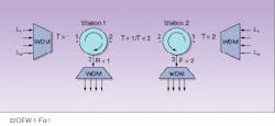
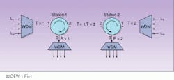
One of the most useful features of an optical circulator is its ability to perform a beamsplitter function on a full-duplex optical signal. For example, an optical circulator has the means to discriminate inbound and outbound signal paths on Port 2 in such a way that inbound signals are routed to the Port 3 interface and outbound signals are routed from the Port 1 interface without interference (see Fig. 1).
Another useful feature is the low pass-through insertion loss of a circulator, typically less than 1 dB for a three-port device. This is in contrast to its coupler counterpart, which can have losses in excess of 3 dB for 50:50 signal-splitter configurations. The incremental savings in insertion loss per circulator device become significant when considered in the planning and design of a system-gain budget for an optical transmission system.
Transmission equipment needed to compensate for signal coupler losses can be costly and complex. On the transmit side, additional amplifiers may be needed to compensate for accumulated coupler losses. On the receive side, complex data de tection or error-correction coding schemes and additional low-noise amplifiers may be needed to enhance low threshold signal levels.
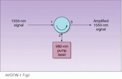
Another interesting feature of circulators is the ability to perform an integral isolator function. Consecutive ports can be viewed as individual isolators with high peak isolation between ports. Thus, a duplex node can be handled by a single circulator, eliminating the need for external isolators to block self-transmitter and transmitter/receiver interference. Accordingly, connection interfaces can be eliminated, improving overall system performance and reliability. A related feature is the ability of an optical circulator to handle high input power levels, which makes them highly attractive for erbium-doped-fiber-amplifier (EDFA) applications (see Fig. 2).
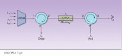
Optical circulators are broadband devices with models that operate at the standard optical-communication wavelengths of 850, 1310, and 1550 nm. This broadband feature makes them very useful in DWDM systems where multiple wavelengths are carried along a single fiber (see Fig. 3). Transparency to specific wavelengths within a standard communication window makes them universal and easily integrated into systemwide equipment.
Finally, optical circulators can be polarization insensitive or polarization maintaining. This gives designers freedom to incorporate them in diverse fiber applications.
Design and construction
Optical-circulator features are best appreciated with an understanding of their basic design principles and construction. The diversity of design results from efforts to develop circuits having minimum pass-through signal losses, maximum port isolation, and manufacturability in large volumes with consistent and reliable performance.
The basic building blocks of an optical circulator are polarization beamsplitters (PBSs), Faraday rotators, and half-wave plates. Secondary components include prism and collimator assembly elements. Polarization beamsplitters separate and combine orthogonally polarized light beams. Faraday rotators and half-wave plates rotate the polarization plane of incoming randomly polarized beams; the former rotator`s action is independent of the propagation direction of the traversing beam, and the latter rotator`s action is dependent on the propagation direction of the traversing beam.
With a suitable combination and arrangement of these building blocks, a randomly polarized light beam entering any given circulator port is separated into its orthogonal components, each of which is fittingly rotated in polarization such that its reconstruction is enabled at the next consecutive port, while being blocked at others.
The actual commercial construction of optical circulators requires novel implementations to achieve high isolation, low insertion loss, low crosstalk, low polarization-dependent loss, and low mode dispersion. The internal elements may be birefringent, waveguide, or thin-film structures. Additionally, the best optical circulators are constructed with epoxy-free optical paths enabling the processing of high-power signals.
Applications and trends
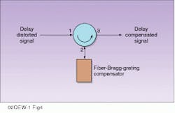
Optical circulators are useful devices in that they are broadband tools for multiple applications with the benefit of reducing system cost and complexity. Along with applications associated with duplex network transmission, WDM add/drops, and EDFAs, circulators can be used for fiber dispersion compensation (see Fig. 4) and in demultiplexers (see Fig. 5).
The optical circulator, like many of its optical-component counterparts, is continually subject to technical improvement and innovation. For simple three-port devices, optical specifications will continue to improve through incremental enhancement of their key specifications such as insertion loss and isolation. Increasing port count while minimizing component footprint will be another step in their evolution, making their integration into DWDM equipment simple and cost-effective.
The most interesting evolution of the circulator will be further integration of functionality. Circulators will likely be integrated with tunable filters to perform wavelength-division add and drop. In addition, circulators eventually will be integrated with optical switches to perform time-division add and drop. Then, both functions likely will be integrated, making the integrated circulator a building block for all-optical network equipment. o
FIGURE 1. For a duplex network transmission application, circulators C1 and C2 are situated at Station 1 and Station 2, respectively, along a common long-haul optical path. A full-duplex optical signal interfaces at Port 2 of each device at each station. At Station 1, C1 Port 1 is used as the forward path transmit interface for an incoming multiwavelength signal, TX1, which is directed out C1 Port 2 for transmission to Station 2. At the same time, C1 Port 2 is used as the Station 1 receive interface for signal RX2 arriving from Station 2. A similar scenario takes place at Station 2.
FIGURE 2. For an EDFA application, an optical signal at 1550 nm is input to Port 1 of a three-port circulator and directed to Port 2. The optical circulator`s tolerance for strong signal level and its small insertion loss make it an ideal device for this application. The weak 1550-nm signal is pumped by a 980-nm external source at Port 2. The amplified 1550-nm signal is reflected back from Port 2 to Port 3 for final output.
FIGURE 3. For a WDM add/drop application, a Bragg grating is placed in series between two circulators to create a WDM add/drop function. An incoming multiwavelength signal is directed to C1 Port 1 at the receive station. All but one of the signal wavelengths, l-1, are passed forward to C2 Port 2. Wavelength signal l-1 is reflected at the l-I grating back into C1 Port 2. This reflected signal at C1 Port 2 now becomes the drop channel and is singularly directed to C1 Port 3. All remaining signal wavelengths continue forward to C2 Port 2. Next, a new l-I signal is added to the traversing multiwavelength signal at C2 Port 1 by a subsequent reflection by the Bragg grating at C2 Port 2, which is then reflected back to C2 Port 3 along with the remaining multiple wavelength signals.
FIGURE 4. For a fiber dispersion-compensation application, a fiber Bragg grating is connected to Port 2 of an optical circulator. The distorted optical signal at Port 1 is conditioned with appropriate compensation by passing to the compensating Bragg grating on Port 2 and then reflected back out to Port 3 with improved delay distortion.
How a circulator works
An incoming linearly polarized light beam, L1, enters circulator Port 1 through a fiber collimator assembly that focuses the beam for the polarization beamsplitter (PBS1; see figure). PBS1 decomposes the collimated light beam into two beams of orthogonal electric-field vectors, L1V and L1H, and directs these orthogonal beams to different directions depending on their direction of polarization. PBS1 reflects the L1V polarized beam to Prism 1 while transmitting through the L1H polarized beam to Prism 2. Prism 1 and Prism 2 deflect L1V and L1H, respectively, in the direction of PBS2.
In series with each prism and polarization beamsplitter is a half-wave plate and Faraday rotator pair. The half-wave plate and the Faraday rotator pair are configured so that their respective polarization rotator actions are equal and opposite, resulting in a net zero polarization rotation for the light beam L1V propagating in the direction from half-wave plate to Faraday rotator. For a light beam traversing from the opposite direction, its net polarization will be shifted by 90° because of the nature of the half-wave plate. Because PBS1 and PBS2 are similarly constructed to reflect V polarizations and to transmit through H polarizations, L1V is again reflected at PBS2 while L1H is transmitted through it, then summed to reconstruct the composite L1 signal at Port 2.
In a similar fashion, a different linearly polarized light beam, L2, enters circulator Port 2 through a fiber collimator assembly and is similarly decomposed by PBS2 into two orthogonally polarized field vectors, L2V and L2H. PBS2 reflects the L2V polarized beam to Prism 1 while transmitting through the L2H polarized beam to Prism 2. Because L2V and L2H are propagating in the opposite direction as L1V and L1H (from Faraday rotator to half-wave plate), their net polarizations are rotated 90° before reaching PBS1. Prism 1 and Prism 2 deflect these beams in the direction of PBS1. L2H` is now vertically polarized L2V`, and therefore reflected at PBS1, while L2V` is now horizontally polarized L2H`, and therefore transmitted through PBS1, where they are summed to reconstruct the composite L2 signal at Port 3.
FIGURE 5. For a demultiplexer function application, any number of optical circulators, N, can be cascaded between fiber gratings. At each circulator`s Port 3, a unique wavelength is demultiplexed. The operation of the demultiplexer is similar to the WDM add/drop application described earlier. As the multiwavelength signal passes through each circulator`s Port 1, that signal having its wavelength correspond to that of the Bragg grating is singularly reflected back into circulator Port 2 and dropped at circulator Port 3.
