Rewritable compact disks fill multiple storage needs
Rewritable compact disks fill multiple storage needs
Hardware compatibility and read and write integrity are essential to the success of rewritable data
storage systems.
Winslow Mimnagh
It is now possible to create and rewrite one`s own compact disks (CDs). The new Compact Disc-ReWritable (CD-RW) drives and media introduced in 1997 by Philips Electronics N.V. (Eindhoven, the Netherlands) represented a major breakthrough in optical disk storage. Based on phase-change technology, the CD-RW system allows disks to be written and rewritten many times over. It is therefore a perfect medium for temporary and long-term data storage.
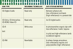
CD-RW is the latest stage in the evolution of compact disk technology. The CD system started life with digital audio compact disks, progressed through CD-ROM (read-only memory), CD-interactive, and video CD to CD-R, a recordable write-once system (see table on p. 208).
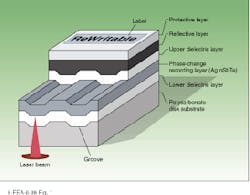
The CD-RW disk consists of a grooved polycarbonate substrate onto which a stack of thin layers is sputtered, followed by a protective lacquer. Usually the stack is made of four layers (see Fig. 1). Some layers can be sputtered in two or three stages. The production equipment used in manufacturing the CD-RW disk is similar to that used for less-complex CD disks, but the sputtering equipment is more sophisticated; at least four chambers are needed to deposit the extra layers.
The dielectric layers in the stack are typically zinc selenide-silicon dioxide (ZnS-SiO2) and serve the purpose of thermally tuning the phase-changing (recording) layer, which allows the disk designers some freedom to adjust the optical characteristics of the disk such as reflection and modulation of the recorded signal. As the disk comes out of the sputtering machine, the recording layer is in an amorphous state. The disk is then put into an initializer, which heats up the recording layer to the point where it crystallizes.
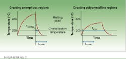
Thus, in its original state, the recording layer of a CD-RW disk is polycrystalline. During writing, a focused laser beam selectively heats areas of the phase-change material near or above its melting temperature (between 500°C and 700°C), so all the atoms in this area can move rapidly in the liquid state. Then, if the material is cooled sufficiently quickly, the random liquid state is `frozen-in` and the so-called amorphous state is obtained. If the temperature of the phase-change layer is kept below the melting temperature but above the crystallization temperature (200°C) for longer than the crystallization time of the phase-change material, the atoms revert back to an ordered, crystalline state (see Fig. 2).
The amorphous and crystalline states have different refractive indices (5.0-2.2i and 4.1-5.1i, respectively) and can therefore be optically distinguished. In the CD-RW system, the amorphous state has a lower reflectance than the crystalline state (typical blank reflections of 3% and 21%, respectively). During read-out the data signal produced from the recorded CD-RW disk is similar to that of a regular CD, making it possible to read CD-RW disks on CD-ROM drives.
Standardized components
Establishment of worldwide standards has made it possible to incorporate writable technologies in CD systems. Standards were necessary because the CD system licensors, Philips and Sony (Tokyo, Japan), were determined to guarantee the hardware compatibility needed to create confidence in the market development. However in order to realize suitable products the industry needed to solve problems such as sufficient laser power at 780 nm, greater efficiencies of the optical pickup unit (OPU), and methods to calibrate and control laser powers at the disk.
Track and speed information and special control information must be embedded on the disks to ensure compatibility between CD writers and readers. Efficient, low-cost disk designs are required by the industry and market alike.
Aluminum gallium arsenide (AlGaAs) semiconductor lasers with output wavelengths near 780 nm are used in CD applications. Conventional CD applications require only very-low-power lasers (10 mW) for read-out. For the CD-RW disk, more power is needed to write and erase, thus maximum output powers are currently either 50 or 60 mW (pulsed with 50% duty cycle and average pulse width of 250 ns). During recording the laser output is modulated at power levels determined by a predefined strategy set by the data to be recorded. The laser in a CD-RW drive has to be pulsed to form well-defined amorphous regions of the desired length. The power level for erasing is used to form the crystalline regions between the amorphous regions.
Improved optical efficiencies from laser to disk in CD-RW drives compared with read-only drives were achieved by use of optical components such as a polarizing beamsplitter and a quarterwave plate (see "How to write again on a CD-RW drive," below). Typically efficiencies for CD-RW drives are between 28% and 33% (compared with only 3% in CD-ROM, or read-only, drives). Further improvements in efficiency are very welcome, and use of antireflection coatings on optical components, beam shapers, more-efficient laser far field, and so forth must be considered.
Guaranteeing integrity of data
For any data storage system to be successful it must guarantee both write and read integrity. This is accomplished with two forms of performance enhancements. The first--read equalization--is in the read-out channel. The optical pick-up system in a CD-RW system has a well-defined and optimized transfer characteristic. However, the diffraction-limited spot and disk characteristics can lead to distortion of the data signal because of the inherent high-frequency roll-off of the optics. This distortion can be compensated for by means of read equalization and can be implemented optically or electrically; in CD-RW drives both can provide wide read-out margins.
Read equalization basically boosts the amplitude of the high-frequency components of the read-out signal while maintaining constant delays over the data frequency range. An analogy is the hearing aid: as people age, a loss of hearing occurs, although not equally over the sound spectrum. Often a loss of 3-6 dB occurs first at frequencies greater than 1 kHz, while hearing at frequencies lower than 10 kHz remains unaffected. A hearing aid compensates for the hearing loss by boosting the amplitude of sound above 1 kHz.
The other form of equalization is write equalization, which can be divided into two categories--thermal compensation and real-time optimum power control (ROPC). In the Philips CD-RW system the write strategies and disk designs have a limited need for thermal compensation. The effects of dust and scratches on the read-out side of the disk are, however, a real threat to write integrity, for particles or marks will impede the light from entering the disk proper and the data signal will be written poorly or not at all. The ROPC procedure compensates for this by monitoring the pit formation process in real time comparing the control signal with a reference signal value in effect during power calibration. When an obstacle obstructs the light from the recording layer of the disk, the control signal differs from the reference value and is adjusted automatically back to the reference value by increasing the output power of the laser.
Today the CD-RW disks are unique, but this will not be the case in the future as disk manufacturers look to product differentiation and lower costs. To provide for disk design flexibility but also ensure compatibility, the CD-RW system allows special data to be encoded in the disk to provide time information over the entire disk. In a reserved area of the disk, other information is added, such as maximum and minimum recording speeds, maximum duration of the disk, and various power control parameters. This information allows CD-RW drives to adjust to the write and read characteristics of each manufacturer`s disks.
Such technical innovations are necessary to ensure data integrity in recording and reading CD-RW disks. As they offer greater compatibility and lower cost, CD-RW products are set to play an important role in renewable mass storage and consumer audio applications. o
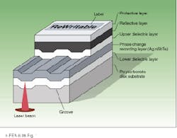
FIGURE 1. Four-layer stack design of rewritable compact disk has a mastered wobbled groove that stores data for servo guidance, timing information, and speed control. The recording layer is based on a crystal-to-amorphous transition in the tellurium (Te) alloy.
FIGURE 2. More energy is needed to write data to a CD-RW disk (converting the polycrystalline material on the recording layer to an amorphous state) than to erase the data (reconverting the material to its crystalline state). The Philips system uses an overwrite strategy that eliminates the need for separate write and erase passes.
How to write again on a CD-RW drive
A PC equipped with a compact disk rewritable (CD-RW) drive makes short work of storing many megabytes of data and permits rewriting data--over and over again. How does such a system work? Simple.
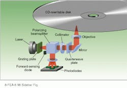
A laser diode in the optical pickup unit emits photons that move through the optical system at the speed of light, traveling first through a polarized beamsplitter from which the light exits linearly polarized (see figure). The photons then move through a collimator and a quarterwave plate, from which the light exits circularly polarized, before it goes through an objective lens.
The lens moves up and down to focus the photons on the CD-RW disk. Some photons are absorbed, others are scattered outside the aperture of the optical system, and some are reflected back from the disk and through the optical system.The returning photons are diverted by the polarizing beamsplitter to the photodetectors. There they create electron-hole pairs and give rise to photocurrents, from which control and data signals are derived for servo control and data decoding.
The magnitude of the sum of the photocurrents indicates that the disk is rewritable and the objective lens is in focus. The servo motor starts to turn and spins up to 3000 rpm. In two seconds, the drive confirms that the disk is CD-RW from special information encoded on it, reads the disk`s data contents, and jumps to the first writable address. The drive`s servo control system deftly moves the light spot radially 5 µm in one direction, finds the groove and then moves in the other direction while the spot follows the spiral groove in the disk for approximately 400 µm. These actions are repeated as the drive awaits further instructions.
Once told which files to save, the control system responds by dropping the motor speed down to 1000 rpm and positioning the light spot at the laser power calibration area on the disk. The motor locks to the wobbled pregroove signal and synchronizes with prerecorded instructions on tracking and speed. When the correct address is read, the write power calibration begins. The laser writes to the disk with ever-higher write powers. It then jumps back to read the modulations of the recorded signals. These data are processed and the optimum write power is found. This and the information for real-time power control is stored in memory.
The servo moves the light spot to the first writable address, controlling the light spot such that it follows the groove and groove wobble. When the correct address is found, the current through the laser is increased and the power out of the laser is controlled to the optimum write power by means of the forward-sensing diode sitting just at the edge of the laser`s near field.
As the drive writes the data to the CD-RW disk, it monitors the recording process by means of the real-time optimum-power control signal. If dust and fingerprints on the underside of the disk prevent the photons from reaching the recording layer, the control signal changes proportionally and the power out of the laser is adjusted to compensate, thus ensuring that the write integrity is maximized. It`s as simple as that!
W. M.
Collimator in CD-RW optical path collects divergent beam of linearly polarized light from the beamsplitter and makes it a parallel beam. Quarterwave plate circularly polarizes the parallel beam, which is imaged onto the disk via a mirror and an objective lens. Reflection from the disk reverses the circular polarization such that the beam passes again through the quarterwave plate and emerges linearly polarized in a plane orthogonal to the polarization plane of the original beam. This change in beam orientation allows the beamsplitter to divert the returning light to the photodiodes and not back into the laser.
