Laser scanning digitizer captures large designs
Laser scanning digitizer captures large designs
Jag S. Gadhok
In many industries the product-design process requires digitization of drawings for input to a computer system and subsequent detailed design work. Small-format digitizers are effective for many applications, but for digitizing large-scale designs of automobiles, aircraft, and other vehicles, the small-format digitizers cannot be used. These large designs are digitized by manual measurement of the line coordinates using calipers and other measuring tools. The data are then entered into the company computer system for archiving and to complete the design effort.
This laborious and time-consuming process is costly and prone to both measurement and data-entry errors. A laser digitizer such as the one developed by Digital Scanning Systems (Santa Rosa, CA) automates the process by providing rapid and highly accurate digitized data in vector format for electronic entry into computer-aided-design (CAD) software and company computer systems. The time and cost savings for product designers and manufacturers is significant. The system can provide a digitization rate of 160 data points per second and an accuracy level of one part in 25,000, with a resolution of one part in 32,000. Drawings and designs up to approximately 80 ¥ 240 in. (2000 ¥ 6000 mm) can be digitized.
System design
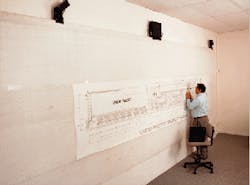
The laser digitizer system is based on resonant laser scanning, a position-sensing technology that uses simple triangulation calculations to achieve high levels of speed and accuracy. Two scanheads, each enclosing a resonant scanner and associated electronics, are mounted on the top of a whiteboard or other drafting/writing surface (see Fig. 1). The scanheads are connected to an interface box that supplies them with power and relays signals gathered by a laser-activated hand-held stylus to data-acquisition boards inside the system controller (a PC or a laptop computer). The data-acquisition boards convert the analog signals to digital data for computer input. The digitization system software installed in the controller then processes the digital data to generate the x,y coordinates of the stylus.
Data acquisition is done with a special stylus or an ordinary dry marker pen equipped with retroreflective tape or collar. To collect the data, two 680-nm diode laser beams--which are scanning just above the board surface--intercept the collar on the stylus (see Fig. 2). Retroreflected laser light from the collar is focused onto a detector in the scanhead, generating an event trigger that records the scan mirror position. The position data from the bidirectional scanning are averaged to locate the centroid of the collar. In addition, the position sensor measures the tangent of the beam`s angular position of contact.
In computing the stylus coordinates, signal processors use simple algebraic math instead of elaborate transcendental functions that slow the data capture rate. The use of resonant laser scanners overcomes the limitations imposed by the unidirectional scanning of the commonly used rotating polygonal mirror scanners. The highly stable bidirectional laser beam scanning, combined with position-sensing technology, produces a high level of resolution and accuracy.
The system scanners also provide exceptional mechanical stability. Instead of using motors with bearings that can fail, the scanners use a cross-flexural pivot rigidly attached to two oscillating scan mirrors. One mirror scans the out-going laser beam; the other deflects the second laser beam to scan the linear-position detector for accurately measuring the angular direction of the scanning beam. The steady periodic motion of the mirrors leads to an ultrastable beam scanning motion through angles greater than 90°.
Each laser scanhead in the digitization system consists of a diode laser operating at 680 nm, a cross-flexure-based resonant scanner with scanning mirror, a parabolic collector, an electro-optical position sensor, a photodetector, and associated electronics. The laser beam is collimated to produce a 2 ¥ 10-mm elliptical beam that passes through a hole in the parabolic collector and impinges on the mirror of the resonant scanner, creating a fan of laser light parallel and close to the whiteboard or writing surface.
The cross-flexural pivot results in an ultrastable laser beam scan motion. The mirror is made to oscillate at a fixed amplitude with an electromagnetic actuator at the resonant frequency of the electromechanical system. A secondary light beam from a diode laser impinges on the same mirror and is focused onto an optical position-sensitive detector.
Reading the output
The output of the position detector and its associated electronics provides a signal that is proportional to the tangent of the angle of the mirror. The scanhead also incorporates a photodetector that is located at the focal point of the parabolic collector. When the scanning laser beam impinges on the retroreflective collar of the stylus, a portion of the laser beam is reflected back to the scanning mirror. This reflected beam is focused by the parabolic collector onto the photodetector. The signal from the photodetector triggers the data-acquisition module residing in the controller to acquire the position signal from the position sensor electronics. These data provide the tangent of the angle of the stylus position when the laser beam encounters the stylus.
The data-acquisition module acquires and digitizes the mirror position signal to 16-bit accuracy at the instant the laser beam encounters the retroreflective collar of the stylus. This module also handles all communication to and from the controller, which processes the data. Digitizer software applies calibration functions to the position sensor measurements to remove any nonlinear effects from them. These calibrated measurements are used to compute the x,y coordinates of the stylus, using triangulation equations.
The digitizing stylus is a mouse with a retroreflective post 0.75 in. in diameter and 3 in. high (see Fig. 3). The mouse makes contact with the drawing surface at three points. The stylus post has a crosshair at the bottom and adjustable magnifying optics at the top end to accurately locate the point. A wireless transmitter located inside the mouse transmits the switch actualizations to a receiver inside the data-acquisition module.
For handwriting applications, a wireless pen-shaped stylus also can be used. The technology can also be used for distance learning and teleconferencing applications. o
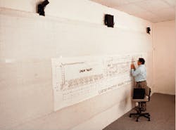
FIGURE 1. Laser-based digitization system, operated here by the author, can transform large-scale hand-drawn designs into digital information for storage or manipulation.
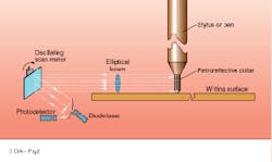
FIGURE 2. Scanning system includes two scanheads, each with a 680-nm diode laser, photodetector, and oscillating scan mirror, and a stylus with retroreflective collar.
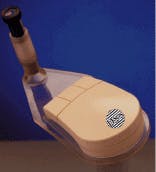
FIGURE 3. Retroreflective collar on 3-in. post (on underside of stylus) is key to fast and accurate digitizing of large-scale designs.
JAG S. GADHOK is president of Digital Scanning Systems, 2345 Circadian Way, Santa Rosa, CA 95407.