Holographic techniques that can record both the phase and amplitude of the light reflected by a diffusely scattering object can be used to generate a true, three-dimensional image.1 Holograms were originally demonstrated by Dennis Gabor in the late 1940s, but significant interest and application of holography did not occur until the 1960s when a convenient source of coherent radiation, in the form of the laser, became available. At approximately the same time, Emmett Leith and Juris Upatnieks solved the twin-image problem associated with Gabor’s original technique through the use of off-axis illumination, thereby generating a surge of activity in the field.
During this burst of interest and activity, several groups realized that two holographic images of an object could be compared by recording them on the same plate. Because each image recorded the phase of the light leaving the illuminated object, small displacements that occurred between exposures produced interference fringes in the reconstructed image. Ideally, a 100% modulation in amplitude was produced by a displacement that is equal to half of the wavelength of the recording beam, making the holographic interferogram a high-resolution record of the movement that occurred between exposures.
During the past three decades, several other types of interferometric holography have been demonstrated, each having advantages for a specific class of measurement. According to a recently published review on the subject,1 the technique has been used in applications that include the inspection of aircraft components, the study of the embryonic behavior in intact incubating eggs, the vibration analysis of reeds and tympanic membranes, and the measurement of time-dependent shrinkage in concrete structures. In each case, a holographic interferogram can show dimensional changes that are difficult to detect via other techniques.
This article describes several techniques for generating an interferometric hologram, along with some representative applications and a look at the potential impact of new hardware and software on the evolution of this field.
Transmission holography makes measurements
Reference to one of the several excellent texts on holographic techniques will quickly convince the reader that high-quality holograms can be produced by a number of different methods.2 For example, holograms that can be reconstructed with a white-light source are typically created using a reflection technique in which a single input beam passes through the holographic medium and is reflected back onto the plate by the object. Because they do not require a laser for viewing, reflection holograms can be found in novelty stores, high-end superhero trading cards, and fine-art galleries.
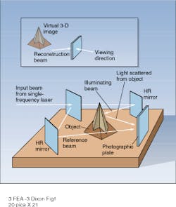
Although reflection techniques also can be used to produce an interferogram, a transmission holography setup is more commonly used (see Fig. 1). In this setup, the output from a single-frequency laser is incident on a beamsplitter that divides it into object and reference beams. After passing through a spatial filter, the reference beam passes through a beam expander and is used to illuminate the holographic plate. In the ideal case, the expanded beam is collimated with phase fronts that are tilted relative to the surface. The second beam is also spatially filtered and is used to illuminate the object.When the relative amplitudes of the object and reference beams are correctly adjusted, the holographic medium (typically a photographic plate) records the amplitude and phase of the light reflected by the object. After processing, illumination of the hologram with the reference beam (or other coherent source) generates a virtual, three-dimensional image of the test object that can be viewed by looking through the hologram (see Fig. 1, inset). During reconstruction, the image seen through the hologram contains all the phase and amplitude information that existed in the light reflected by the sample.
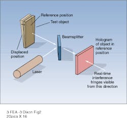
In its widest sense, holographic interferometry describes a set of techniques in which at least one of the interfering beams is produced by a hologram. In the fixed-fringe, or double-exposure, technique, two holograms are recorded on a single plate, and the fringes are produced by interference between the two images during reconstruction. Real-time or live holography produces a continuously varying interference pattern by comparing a holographic reference image with the reflected light from a real sample object (see Fig. 2). Because the phase of the reflected light changes with object position, the fringe pattern that is generated using this technique changes in real time as the surface of the object is moved. Alternatively, fringes can be generated by phase variations in the path between a fixed hologram and a flat reflector, allowing the real-time visualization of thermal and pressure gradients in gas-phase samples.In a third technique known as time average holographic interferometry, a hologram of a vibrating body is recorded with an exposure time that is several times greater than the period of the vibration. During reconstruction, vibrational modes are visible as light and dark patterns on the image of the vibrating object. Mathematically, the amplitude of the reconstructed wave is equal to the complex amplitude of the scattered light integrated over the exposure period. Vibrational nodes that are essentially stationary during this exposure period produce comparatively large scattered amplitudes and appear as bright fringes during reconstruction. While providing qualitative information on the vibrational mode of a structure, time average holographic interferometry produces no information on the relative phases of different points on the object surface.
Noncontact measurement
Most applications of holographic interferometry take advantage of its ability to map minute displacements or changes in refractive index over an extended field of view. In almost all cases, the interference pattern is generated by comparing a hologram of an object taken at one instant in time with a second image that can be real or holographic in nature.
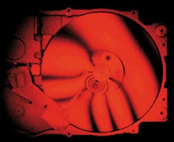
One broad class of applications involves the analysis of solid objects that are subjected to mechanical or thermal stresses (see photo at top of this page). Quantitative analysis of the interference between a hologram of an aluminum plate that is subjected to mechanical and/or thermal stress with a hologram of the object in an unstressed state can be used to calculate fundamental material parameters of the metal. In other cases, qualitative distortions in the fringe pattern of an object may indicate the presence of voids or other structural defects.
In applications of this type, the comparison of the stressed and unstressed states can be made with either double-exposure or real-time techniques. In both cases an accurate measurement re quires the elimination of motion between the plate and sample as stress is applied. With the double-exposure technique, errors due to photographic-plate positioning are eliminated because the holographic medium remains fixed between exposures. Unfortunately, the interference fringes cannot be viewed in real time and a lengthy trial-and-error process is required to optimize the stress on the sample. Too much stress (and, hence, distortion) produces fringes that are closely spaced and difficult to interpret.
With real-time techniques, fringes are always visible because the holographic image is compared to the real object. While superior to the frozen-fringe technique in this respect, live-fringe holography can be used accurately only if the reference hologram can be repositioned to within a few wavelengths of its original location after development. Although not impossible, meeting this requirement is a formidable optomechanical design problem.
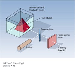
In addition to the measurement of small displacements, holographic interferometry can also be used as a noncontact, three-dimensional measurement technique. Interference fringes corresponding to equidistant contours on an object are produced in a double-exposure hologram in which the wavelength or angle of the beam illuminating the object is changed between exposures. Contour fringes can also be produced by changing the refractive index of the medium around the object between exposures (see Fig. 3).To make a real-time contour map of an object using the method of Fig. 3, the object under study is immersed in a tank of liquid (water, for example), and a reference hologram is recorded. After development, the reference is returned to the real-time plate holder and the refractive index of the liquid changed by adding a small quantity of a liquid with different refractive index. After mixing, live interference fringes corresponding to planes of equidistance from the observer will be visible. Quantitative knowledge of the refractive-index change of the immersion fluid or inclusion of a dimensional reference next to the sample object allow an accurate three-dimensional image to be constructed from the contour fringe pattern. This process is further facilitated by a setup in which the reference beam is collimated and the hologram is recorded and viewed at normal incidence. Under these circumstances, the separation between adjacent fringes in the interference pattern, Dz, is given by
Dz = (l/2)/ (n1- n2)
where n1 and n2 are the refractive indices of the immersion medium during the two exposures.3
The corresponding expression for a properly optimized two-wavelength setup is
Dz = (l1 l2/2)/(l1 - l2)
where l1 and l2 are the two wavelengths used in the process. For frequency-doubled Nd:YAG and Nd:YLF lasers at 532 and 523.5 nm, repectively, this interval is approximately 16 µm.
Wider use of holographic techniques
Depending on personal bias, one can describe interferometric holography as an important tool that has seen little application in industrial settings due to stability requirements and the time delay between the recording and viewing of a hologram that is recorded on a photographic medium4 or as an exciting field that has been revitalized within the past decade by the availability of new laser and computational tools. In both cases, there is agreement that interferometric holography is, at the current time, primarily a research tool.
While good mechanical stability is required for most holographic techniques, the use of pulsed laser sources can relax this requirement somewhat. Historically, pulsed ruby lasers were used for this application despite numerous drawbacks. Frequency-doubled Nd:YAG lasers, operating at 532 or 660 nm, offer an attractive alternative to the chromium-based sources, especially if the energy required for a single-pulse exposure can be reached with diode pumping. Even in cases where this is not possible, the combination of a diode-pumped master oscillator with a flash-pumped power amplifier in either an injection-seeded or master oscillator-power amplifier configuration is an attractive alternative to a ruby laser.
Continuous-wave exposure does little to reduce the stability requirements for holographic recording but does yield advantages with repect to source coherence and reduced hardware complexity. Currently, frequency-doubled Nd:YAG lasers, operating at power levels as high as 0.5 W, are an attractive alternative to the argon-ion lasers that have often been used for CW recording. In addition to longer coherence lengths, the high efficiency of the solid-state source eliminates the requirement for a dedicated cooling line and three-phase power.
While processing time will remain an issue in the foreseeable future, the use of new photopolymer materials can eliminate the need for wet chemicals. For example, an image recorded on Dupont`s HRF-610 material is cured by exposure to ultraviolet (UV) light and ‘fixed’ by baking at elevated temperature. Diffraction efficiencies exceeding 80% have been demonstrated for holographic gratings that were produced by exposure to a HeNe laser at 632 nm, cured by 5-min exposure to a 4-W UV lamp, and subsequently baked at 120°C for 2 h.5 Reflection holograms stored in this material appear to be of higher quality than those recorded using conventional photographic emulsions.
Holographic interferometry has also benefited greatly from the increased power of computer workstations. In those cases where it is desirable to extract quantitative information from the interference pattern, computer analysis can significantly reduce the time and effort needed. As with the traditional interferometers used in optical metrology, the continued development of new hardware/software tools will significantly broaden the range of applications for holographic techniques.
Along with many other laser-based techniques, holographic interferometry is a powerful tool that will remain in the research laboratory until an economical, easy-to-operate system is introduced. The design of such a system will be aided by improvements in digital-processing capability in addition to the availability of compact, low-cost single-frequency lasers and improved holographic recording media. Continued progress in each of these areas may ultimately lead to the widespread use of holographic interferometry for quality control and other nondestructive-testing applications.
REFERENCES
1. P. K. Rastogi, Holographic Interferometry, Principles and Methods, Springer-Verlag, Berlin (1994).
2. H. M. Smith, Principles of Holography, 2nd ed., John Wiley & Sons, New York, NY (1975).
3. P. K. Rastogi, "Holographic interferometry—an important tool in nondestructive measurement and testing" in Optical Measurement Techniques and Applications, P. K. Rastogi, ed., Artech House, Norwood, MA (1997), p. 111.
4. G. Cloud, Optical Methods of Engineering Analysis, Cambridge University Press, New York, NY (1995), p. 343.
5. E. S. Dimova and M. Kavehrad, SPIE Proc. 2406, 386 (1995).


