Mature optical technologies back lasercomm aspirations
Mature optical technologies back lasercomm aspirations
Visions of broadband wireless in the sky have attracted high-powered investors and military technology, but the keys to commercial success lie in ease of manufacture.
Joseph D. Fargnoli
The idea of providing wireless voice, video, HDTV, and Internet data on demand with the service quality of a fiber link has attracted some of the world`s wealthiest investors. Teledesic, a venture funded by Bill Gates, Craig McCaw, and others, plans to use laser frequencies--not radio frequencies--to carry broadband data across a global constellation of low-Earth-orbit (LEO) satellites.
Although largely untested in space outside of the military, the enabling technologies for intersatellite laser communications (lasercomm) have matured with development of ultrastable laser sources, novel beamsteering devices, high-data-rate receivers, and advanced space-qualified communications electronics. Behind these technological advances lies the greatest driver of all--the relentless market demand for instantaneous access to information delivered inexpensively and ubiquitously.
The advantage of a lasercomm frequency over a radio frequency (RF) stems from the characteristic of its wavelength. Many times shorter than RF, laser wavelengths can pack megabits to gigabits of packet data onto a narrow, concentrated beam that can produce a brighter spot (higher gain) at the receiving satellite`s optical antenna for significantly less input power. Lower power requirements reduce support hardware size and weight with follow-on savings in payload launch costs.
Despite these advantages, a designer`s key challenge is to ensure that each optical terminal can transfer a thin light beam efficiently to another satellite terminal thousands of kilometers away. At issue is the ability of two cooperating satellite terminals in the same or adjacent orbital plane to locate one another, align their optical antennas to within fractions of microradians, lock on, and then track and maintain the free-space link during the data transfer.
For the manufacturing engineer, the issue becomes one of cost-effective high-volume production. In the case of the proposed Teledesic network, tens to hundreds of satellites could each carry multiple lasercomm terminals. New design-for-manufacturability concepts and practices will have to be devised to fabricate many of the key components, including the high-quality optics that will give a large number of terminals the required precision and durability to perform in a space environment (see "Designing for manufacturability," p. S8).
System configuration
A free-space laser communications terminal consists of several primary subsystems. The transmitting laser and associated drive electronics convert the input electronic signal into a laser signal, and the optical antenna routes signals from the transmit laser to free space and channels the received signal and any acquisition and tracking signals to their appropriate detectors. A point-ahead mirror and fast and slow steering mechanisms aid in the acquisition and tracking process. The receive detector and processing electronics convert the received laser signal into a suitable electronic signal, acquisition and tracking electronics provide control mechanisms based on the feedback from the appropriate detectors. Finally the communication and control electronics handle all communications signal processing as well as allowing the host vehicle to control the terminal.
The optical link equation
The objective is to establish a reliable, low bit-error rate `link` between cooperating satellites. In the case of Teledesic`s LEO satellite constellation, the intersatellite distance is likely under 10,000 km. Over greater distances, free-space range loss will rise, and link closure will become more difficult. Distances vary for geostationary and medium Earth orbit intersatellite links, space-to-ground communications, anticipated deep-space probes, and eventually planet-to-planet communications (such as Earth to Mars, or Moon to Jupiter).
To identify all sources of link degradation and gains that can affect the received signal level, the designer uses a link equation, expressed as
Pr = Pt ¥ Gt ¥ Tt ¥ LR ¥ Gr ¥ Tr
where Pr is the received signal power, Pt is the transmitted signal power, Gt and Gr are the effective transmit and receive gain (driven by the aperture size and the wavelength), Tt and Tr are the efficiency loss associated with the transmitter and receiver (driven by optical throughput), and LR is the free space range loss (driven by the wavelength and the range between satellites). With this equation, the designer can calculate the necessary technical requirements and trade-offs of each subsystem to achieve optimum system bit-error rate performance.
The optical antenna
One of the key subsystems involved in this trade-off process is the optical antenna, or optical telescope, which can have many different configurations (see figureon p. S7). The number and diversity of optical elements in the optical telescope is enormous. The largest optic is typically the 0.1- to 0.5-m-diameter telescope primary mirror or the slow-steering mirror, depending on the architecture. The smallest element is usually the millimeter-sized fiber interface optic, which directs the laser signal into the micron-sized receive fiber core or detector. In between lie complex dichroic beamsplitters and ruggedized athermalized lens cell assemblies. Sometimes, a solar exclusion window protects the entire antenna and detectors from baking or warping when pointing into the sun. All are mounted in a precise ultrastable structure to maintain microradian alignment between paths.
Depending on the application, optical antenna materials may include silicon carbide, ULE, Zerodur, silicon, conventional glasses, or those suitable for diffractive optics or diamond-turned snap-together technologies.
Transmission and receiving
The purpose of the transmit path is to emit a precisely shaped beam that will deliver maximum energy to the receiving satellite. This, in turn, must capture the energy as efficiently as possible through its receive path. One telescope may double as both transmitter and receiver, or it may be desirable to use separate telescopes for each function.
A diode laser transmitter generates an optical signal beam by converting the electronic data-carrying signal into an optical signal--typically around 1 W in strength for LEO networks. This energy can be fiber-coupled to the optical antenna. A small point-ahead mirror adjusts the direction of the signal by taking into account the relative velocity of both satellites and the finite speed of light. The signal is then sent into the telescope, which expands the signal into the required transmit beam, and sends it across free space. At the receiving antenna, the optical signal--now reduced to the one-nanowatt range--is relayed to the detector and converted back to an electrical signal for processing by the communication electronics.
The vast energy range between the send and receive signals, typically about nine orders of magnitude, creates obvious challenges in terms of the optical design of the system. Telescopes that combine transmitter and receiver into one unit must isolate the incoming and outgoing signals by at least an additional 10 dB to limit interference. Often, optical isolation is provided by wavelength, polarization, or spatial means. In addition, such low return signals necessitate careful stray-light design with extremely low micro-roughness optical surfaces.
To maximize signal strength in the far field, the designer must specify the wavefront quality of the transmitting optics. High-quality optics, as free as possible from aberrations and mechanical stresses, produce a laser beam with low transmitted wavefront error. The lower the error, the more intense the beam at the receiving antenna. Given the number of surfaces needed to form beams and system wavefront specification of around l/10 rms, the component specs can end up on the order of l/100 rms (at the operating wavelength). Fewer elements with complex transmissive designs and efficient antireflective coatings ensure maximum throughput in a space environment.
Acquisition and tracking
Alignment of the laser beam transmission path is both critical and challenging. Across thousands of kilometers, a typical optical antenna in low Earth orbit will need to point and lock the beam onto an aperture fractions of a meter in diameter. Point-to-point accuracy of this dimension requires knowing precisely (within micro-radians) the location of both transmitting and receiving apertures relative to each other.
From data provided by the satellite, the terminal begins the process of acquiring a lock with the target satellite terminal by searching within an initial region of uncertainty--usually about a 1° cone. A defocused beacon signal is used either to cover the entire region of uncertainty or to `paint` the region with multiple linear or conical scans. Once the cooperating satellite has been "acquired," control is turned over to the fine-tracking system, which uses optics to create a wide spot for control on the acquisition sensor, either a quad cell or a charge-coupled device.
The term "tracking" refers to the antenna`s ability to compensate for satellite-induced pointing errors in order to maintain the signal link with a cooperative satellite terminal. Jitter from the satellite platform is the dominant factor that may force a terminal to lose track and break the link. Because a gimbaled telescope or scanning flat mirror is too big to respond rapidly to detected pointing errors, a track beamsteering mechanism consisting of a high-reflectance mirror driven in two axes is placed directly in the path of the transmit/receive path. The beamsteerer is close-loop-controlled to respond to disturbance frequencies between 100 and 1000 Hz.
Optical quality issues
Quality requirements place optics for laser communications terminals into two broad categories--specialized or commercially manufactured. Specialized elements include the primary mirror and other low-wavefront-error optics in the telescope. These optics require high-end design and computer-controlled manufacturing processes to generate initial surface figure and then converge the surfaces to atomic-level accuracy via small-tool polishing and ion figuring processes. Primary mirrors larger than 0.1 m in diameter can be lightweighted by cutting a honeycomb core and fusing mirror faceplates to either side. Facilities that make specialized optics will have to accommodate batch processing of components for faster throughput.
Depending on the optical requirements, designers can resort to commercial-class elements. Established fabricators can produce high-departure aspheric optics in quantity with precision glass-molding technology, which uses precision diamond-turned "nubbins" to mold the optics under heat and pressure. Alternatively, diamond-turned snap-together manufacturing processes also can be used for small telescope and assembly optics.
Lasers and optoelectronics appear set to establish the next generation of data communications in a free-space environment, whether interorbit, intraorbit, space-to-ground, or ground-to-ground. Whether this happens depends on the extent to which the optics industry can cost-effectively mass-produce the complex laser communications equipment to ensure commercial profitability. o

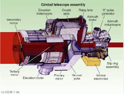
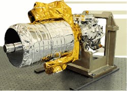
Designed by Eastman Kodak Company, this Ritchey-Cretien Cassegrain optical communications telescope uses a Coudé optical path to allow 2-axis gimbaling for course pointing. The 190-mm-diameter telescope with < 50-mm-diameter central obstruction weighs less than 9 lb. Photo is of a flight-qualified gimbaled telescope assembly designed, manufactured, and tested by Eastman Kodak for the US Air Force`s DSP lasercomm program.
JOSEPH D. FARGNOLI is a senior electro-optical systems engineer in Commercial & Government Systems at Eastman Kodak Co., 800 Lee Rd., Rochester, NY 14650-3118; e-mail: [email protected].
Designing for manufacturability
Like so many advanced technologies today, free-space laser communications technology was spearheaded by the government for military applications. Deployed systems usually carried small numbers of laser terminals and relied on hand-crafted manufacturing processes to manually align and mount the sensitive optical elements with high precision. For commercial broadband constellations featuring tens and possibly hundreds of satellites, the manual approach is no longer viable. To be profitable in a mid-to-high-volume setting, Teledesic and others will have to embrace a design-for-manufacturability concept with automated production line methodologies.
One such approach practiced by Kodak is called Flexible Robotic Assembly Metrology (FRAM). Used for mid-volume assembly of sensitive electro-optical commercial products, FRAM builds the precision and complexity into the assembly test station rather than the component that holds the optic. By leaving the optical elements as loosely toleranced items, FRAM enables an operator using stepped motor controlled positioners with integral interferometric feedback to align critical optical elements quickly, accurately, and at greatly reduced per-item cost. Once aligned, subassemblies are bonded in place with a quick-cure adhesive such as UV cement. A visual check and printed record verify alignment.
Automated assembly techniques such as Flexible Robotic Assembly Metrology (FRAM) will enable cost-effective high-volume assembly of complex electro-optical systems. Previously, laser communications terminals were assembled manually.
J. F.