ADAPTIVE OPTICS: Index matching offers a low-cost route to complex optics
A novel technique allows parameters for turbulence and hardware to be changed to test and optimize performance of adaptive-optics systems.
STEVEN M. EBSTEIN
During the last decade, optical fabrication has changed significantly because of the introduction of techniques that enable economical production of complex aspherical and diffractive elements. An index-matching technique that we are developing allows a precise optical phase to be fabricated with relatively inexpensive equipment.1
To date, one application-the testing of adaptive-optics systems-stands out for this technique, which has become the most common way to make phase plates that simulate atmospheric turbulence. This application originally stimulated our development of a fabrication technique to accurately and inexpensively model atmospheric propagation in the laboratory.2 Several other parties independently discovered the same approach to optical fabrication and some of them were also working on making phase plates.3, 4, 5 We refer to our method as Near-Index-Match optics.
Adaptive optics
Light propagation over long paths through the atmosphere can affect the quality of the propagated beam. Density and water-vapor concentration fluctuations, resulting from turbulent mixing in the atmosphere, in turn produce local changes in the refractive index of the atmosphere. Although they are locally small, when integrated over a long enough path, these index fluctuations cause significant phase aberrations. Clear air turbulence is usually described by a Kolmogorov spectrum with a strength characterized by a refractive-index structure coefficient (CN2) that varies with altitude.6 Integrated over a propagation path, the turbulence strength can be characterized by a transverse coherence length, r0, as described by Fried.7 When a beam with phase aberrations propagates some distance, intensity variations or scintillation occurs because of lensing effects of the upstream phase variations.
Adaptive optics (AO) is a technique for measuring and compensating for the aberrations due to atmospheric turbulence. The distortions are sensed with wavefront and intensity sensors (WFS) and compensated with adaptive optical elements such as deformable mirrors (DM). Adaptive-optics systems are rather complex control systems whose performance depends on numerous fundamental and practical limitations, as well as the details of the turbulent medium. Some of these factors include the division of the beam into smaller subapertures that are sampled by the WFS and corrected with a DM, the light throughput and signal-to-noise ratio (S/N) of the WFS, the actual shape achieved by the DM due to the influence of mechanical stresses and constraints, and the time response of the WFS and DM.
Since the 1970s, scientists have constructed complex numerical models of time-dependent propagation through the turbulent atmosphere and of the response of AO systems.8 These models were generated for scenarios involving either imaging or laser-beam propagation through the atmosphere, in which beam control using AO is useful. Applications include astronomical and surveillance imaging, laser communications, and high-energy laser weapons. Such computer models are very useful in predicting performance, developing requirements, and designing systems for particular turbulence conditions.
Phase screens
Construction of such models usually proceeds through several steps. The propagation path is broken down into discrete layers and a transverse grid is used to model the beam. To adequately sample the turbulent phase and the propagated beam for apertures and turbulence strengths of interest, the transverse grid size ranges typically from 256 × 256 to 1024 × 1024. Sample realizations of phase screens are numerically generated. This is typically done by taking an array of circular complex Gaussian random deviates with amplitudes that correspond to the square root of the spatial power spectrum of turbulence. An inverse Fourier transform is then performed to realize the phase screen in the spatial domain.
To simulate the time evolution of turbulence, phase layers or screens larger than the computational grid are typically generated and translated through the beam with a unique velocity for each screen. This corresponds to how the wind would move a fixed layer (Taylor turbulence) through a beam, which is a simplification of how the real atmosphere behaves.
Numerical simulations are only as good as the correspondence of the computer model with the hardware. Just as with other engineering disciplines, it is usually necessary to perform AO system tests under controlled conditions with real hardware. The performance of the WFS and DM can be tested in the laboratory, and the effect of the computer control can be measured. Parameters of the turbulence and the hardware can be changed, and the resulting difference in performance can be measured and the system can be optimized.
An ideal setup models the turbulent atmosphere with several phase screens, just like the numerical simulation (see Fig. 1). Because of practical limitations, however, laboratory atmospheres usually have fewer layers than computer models. The basic effects due to a distributed atmosphere-scintillation that develops after propagation and anisoplanatism (a different distortion for light propagating at different angles)-can be captured with a two-layer model. Once a phase screen is fabricated, it is difficult to change its strength. However, turbulence strength can be varied by magnifying or demagnifying the beam, effectively changing the ratio D/r0, of beam diameter to coherence length.
Physical models
Just as computer models translate the phase screen to simulate time evolution, a physical model can move the phase screen to simulate spatial effects. A convenient way to do this is to make round, annular phase screens that are rotated to give time-varying phase distortions across a fixed beam. A multilayer physical model can have each layer rotate at a different speed to simulate the variation in wind speed along the propagation path.
The most challenging part of the simulation is to generate physical realizations of phase screens with statistics that reflect real atmospheric turbulence. The fabrication process must have high dynamic range to accurately model a range of optical path differences, covering tens of microns peak-to-valley, with subwavelength precision. Good spatial resolution is also required to represent the range of spatial frequencies present in atmospheric turbulence.
Several approaches have been used to fabricate such phase screens.9 To make phase screens from hard optical materials, techniques like photolithographic etching, ion milling, or ion exchange can be used. These techniques tend to have high capital and/or tooling costs but can produce parts with little dispersion in traditional optical materials that withstand high powers.
Near-Index-Match optics
A pseudo-random surface is either machined in an optical plastic, such as acrylic, with a conventional machine tool, or set in the plastic using a mold that need not have an optical quality surface. A second optical polymer is cast against the first. The two materials have a small index difference, ∆n = n2 - n1. The optical path difference (OPD) at any point (x) on the optic is the product of the relief height, h(x), and ∆n, which effectively demagnifies the relief height (see Fig. 2). For a ∆n of 0.02 and typical machine tool accuracy of 0.0002 in., the resulting OPD is accurate to λ/6 at 633 nm.
A variety of aspherical and diffractive phases can be realized with these optics.10, 11 If the pair of materials have dispersions satisfying a matching condition, a diffractive optic with achromatic phase can be realized that has high diffraction efficiency over a broad spectral range.12
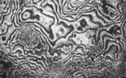
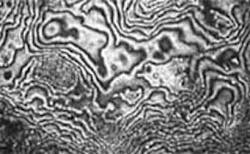
The exterior surfaces of the optic must be of optical quality, and are fabricated conventionally or by replicating an optical-quality surface. We typically accomplish this by sandwiching the Near-Index-Match optic between two high-quality glass windows as a cost-effective means of producing a phase screen that has arcsecond parallelism and high-quality exterior optical surfaces with antireflection coatings. The resulting phase screen has a detailed OPD with accurate statistics (see photo, p. 117).13
The surface profile typically takes a phase specification on a 4096 × 4096 grid, scaled to account for ∆n. For a typical ∆n of 0.02, our machine precision corresponds to λ/25 at 633 nm and is accurate to λ/6. Although it takes hours to machine a large surface, there is negligible cost for tooling, so each phase screen can have a different surface. This is very useful when there is a need to simulate a multiple-layer atmosphere where each layer has different statistics.
A complete system requires phase screens, motorized rotary stages to produce time-varying turbulence, and a motor controller. Our company and others have designed motorized rotary stages with large clear apertures to rotate round, annular phase plates and corresponding controllers.13 This approach is less expensive than what would seem a simpler approach-making phase screens with a center hole for a motor-because of the increased cost of the exterior windows.
For atmospheric simulation, the motion control is fairly simple. Adaptive-optics systems are tested with static or dynamic input. For a static test with multiple realizations, the phase screens can be moved from point-to-point. To test the system’s dynamic response, each screen can be rotated with a constant speed that is unique to each layer. To simulate strong turbulence, this can require rotation rates of several hundred rpm. The resulting system offers the AO system designer the opportunity to test and tweak equipment with a laboratory setup that is well characterized and accurately simulates atmospheric turbulence.❏
REFERENCES
1. S.M. Ebstein, Optics Lett.21, 1454 (1996).
2. S.M. Ebstein, Method and Apparatus for Changing the Focal Length of an Optical System, U.S. Patent 5,091,801 (1992).
3. M. Hercher, Opt. Eng.21(3) SR-064 (May/June 1982).
4. A.B. Naffarate, Appl. Optics22(16) 2400 (1983).
5. T.A. Rhoadarmer, A. Troy, J.R.P. Angel, Appl. Optics40(18) 2946 (2001).
6. V.I. Tatarskii, Wave propagation in a turbulent medium, translated from the Russian by R.A. Silverman, McGraw-Hill, New York, Toronto, London, 1961; second ed.: Dover Publications (New York 1967).
7. D.L. Fried, J. Opt. Soc. Amer.56, 1372 (1966).
8. J.A. Fleck, J.R. Morris, M.D. Feit, Appl. Phys.10, 129 (1976).
9. DJ Butler, E Marchetti, J Bahr, W Xu, S Hippler, Proc SPIE 4839: 623-4 (2003).
10. S.M. Ebstein, Proc. SPIE 4443, 66 (2001).
11. S.M. Ebstein, Proc. SPIE 4493, 150 (2001).
12. S.M. Ebstein, Achromatic Diffractive Optic, U.S. Patent 5,734,502 (1998).
13. S.V. Mantravadi, T.A. Rhoadarmer, R.S. Glas, Proc SPIE 5553, 290 (2004).
STEVEN M. EBSTEIN is president of Lexitek, 14 Mica Lane #6, Wellesley, MA 02481; e-mail: [email protected]; www.lexitek.com.


