Miniature Displays: Optical engines drive advances in LCOS near-to-eye displays
In various forms, liquid-crystal-on-silicon displays with near-to-eye optics are useful for applications ranging from riflescopes to computer gaming.
MILLER SCHUCK
Microdisplay technology has held the promise of large images in small packages for more than two decades.1 As manufacturers improved the performance of the display itself, product developers struggled at a slower pace with the optical technology required to make use of microdisplays in their specific applications. Many military and medical applications (for example, rangefinding and microscopy) require extremely bright information overlaid on the background scenery. Consumer applications have thresholds for cost, weight, size, and performance that make finding good optical-design points difficult at best. Our experience in developing both liquid-crystal-on-silicon (LCOS) microdisplays and near-to-eye (NTE) optics for nearly a decade has resulted in optical engines that meet the requirements of specific applications.
Three variations
Three examples of optical engines designed for near-to-eye (NTE) applications use a Syntax-Brillian SVGA LCOS microdisplay. One engine is an illumination system (or “frontlight”) intended for applications requiring a very bright image from the display source. These applications include riflescopes and see-through head-mounted displays (HMDs) in which reconfigurable information (such as range and a targeting reticle) is overlaid onto the external environment. This information is generally monochromatic (for example, red) to enhance the color contrast between the outside scene and overlay information. We have achieved a 1000 fL (foot-Lamberts; a measure of luminance) red monochrome image in a package that is less than 27.5 cm3 in volume. The frontlight is alternatively capable of presenting a 200 fL full-color image with changes in software and LED drive current.
Another engine is intended for low-cost, lightweight portable applications, such as head-mounted displays for gaming, portable video players, and DVD players. This turnkey module includes an all-plastic eyepiece and lightweight illumination and polarization components. The module presents a 42 in. diagonal, full-color, SVGA image at 2 m image distance in a 26 cm3 package weighing 17 g. Binocular HMD models using the monocular engine have been developed with sub-100 g weight, a significant threshold for user comfort.
Finally, an engine module intended for electronic camera viewfinders (EVFs) has an all-plastic triplet eyepiece with a diopter adjustment range of +1 to -3 diopters and presents a 39 in. diagonal full-color SVGA image at 2 m in a 31 cm3 package.
Frontlight
Near-to-eye devices produce a virtual image that is directly imaged to the retina of a user’s eye. Because there is no screen in the optical path to diffuse light (and increase the system etendue), NTE devices have a significant advantage in brightness over front- or rear-projection systems and can produce images an order of magnitude brighter than typical laptop monitors. The frontlight was designed to produce extremely bright images in a compact package.
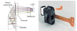
The frontlight is based on a patented total-internal-reflection (TIR) prism.2 Lambertian light from a single tricolor light-emitting-diode (LED) package is collected by a nonimaging reflector (see Fig. 1). For the most efficient light transfer in a small package, Kohler-illumination principles are used to image the output aperture of the nonimaging reflector at the exit pupil of the optical system. In this case, the imaging path is required to be telecentric at the display which, in turn, limits the diagonal field of view (FOV) of the frontlight to approximately 28°. The illumination path includes a Fresnel lens. A dichroic polarizer film prepolarizes the input light before it enters the TIR prism. Once inside the prism, the light path is folded by reflections from a mirror, the TIR surface of the prism, and a wire-grid polarizing beamsplitter. The PBS ensures high contrast over the large skew-ray angles inside the prism. Light reflected from the display is analyzed by the polarizing beamsplitter and a second dichroic-polarizer film. The light passes to the imaging system through an auxiliary prism.
A significant advantage of the TIR prism assembly is the thinness of the prism assembly along the imaging path (6.5 mm). The thin glass optical path allows for a short back focal length in the imaging optics, a significant design advantage. In some instances, a field lens is used at the output of the frontlight assembly for telecentric imaging at the display. Telecentric imaging provides the highest contrast over the entire imaging area. In each design case, the imaging and illumination systems must be matched (by collocating the imaging entrance pupil and illumination exit pupil) for efficient transfer of light.
Frontlight optical performance is measured using a spectroradiometer and an eyepiece lens. The eyepiece is positioned in a fixture such that the frontlight image is visible at infinity. The exit pupil of the eyepiece is collocated with the entrance pupil of the spectroradiometer, ensuring the entrance pupil is properly filled and the measurements are accurate. In addition, the frontlight has been tested under pyrotechnic shock conditions (ten 300 G pulses of 1 ms duration) and over a -25°F to +140°F operating-temperature range. The LED reliability (time to half-brightness) is estimated to be greater than 70,000 hours. The display has a lifetime of greater than 30,000 hours.
Monocular NTE module
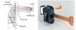
The monocular module consists of an eyepiece, LED-illumination optics, polarization optics, a display, external housing, and flex connector (see Fig. 2). The eyepiece is an all-plastic two-element design that takes advantage of aspheric surfaces and a diffractive optical element (DOE) in the mold tooling. The polarizing beamsplitter is also a plastic component. The plastic elements contribute to the low weight (17 g) and a low bill-of-materials cost for the module.
Diffractive optical elements formed on a surface of a lens can provide powerful color correction (via the element’s negative dispersion) and general aberration correction. If not properly implemented, DOEs can produce undesirable haze in the image and lowered contrast as a result of low diffraction efficiency. Variables affecting the DOE diffraction efficiency include wavelength, angle of incidence, material index, facet step height, and form.
We evaluated the diffraction effects at the edge of the field and pupil in the eyepiece design by simulating a periodic blazed grating on an acrylic substrate. Typical angles of incidence for light at the grating were determined by ray-tracing several eyepiece lens designs. The period of the grating was fixed to the spacing of the diffractive facets at the location where the marginal ray from the corner of the display intersects the diffractive surface of the eyepiece lens. Only s-polarized illumination was simulated because p and s give very similar results in this case. The diffraction efficiency for the linear blazed grating was then calculated.
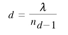
Diffraction efficiency is a strong function of grating depth. Grating depth for the first order is determined by:
where λ is the design wavelength and nd is the index of refraction at the design wavelength. The diffraction efficiencies for typical red, green, and blue LED wavelengths were calculated, then photopically weighted and summed to determine an optimum polychromatic facet height (see Fig. 2). In the case of acrylic, the optimum polychromatic facet height is 1.1 µm. State-of-the-art diffractive molders can hold this step height to 1.1 ± 0.1 µm with proper controls.
Another strong contributor to diffraction efficiency is the angle of incidence (AOI) at which the ray enters or exits the DOE. The diffraction efficiency for red illumination increases with increasing AOI, while blue diffraction efficiency decreases with increasing AOI. We photopically weighted and summed the diffraction efficiencies for typical LED wavelengths to determine an optimum AOI for polychromatic light at the location where the marginal ray from the corner of the display intersects the diffractive surface of the eyepiece lens. This ensured the highest photopic diffraction efficiency over the entire virtual image.
Given the high transmission of the eyepiece configuration (arising from beamsplitting arrangements), we abandoned Kohler illumination for this module, settling instead on a more-diffuse LED lighting arrangement.3 The diffuse lighting creates a larger illumination eyebox and a more familiar magnifier-like optic. The eyebox size was measured to be 15 × 15 mm. The imaging exit pupil was measured by addressing a resolution pattern to the module and viewing that pattern with a CCD camera. The camera entrance pupil is located at the module exit pupil location, and is translated laterally over the eyebox. Locations where the imaging begins to degrade are recorded to determine the exit-pupil extent.4 The imaging exit pupil was measured to be 10 mm wide by 8 mm high.
EVF module with diopter adjust
Some applications, such as camera electronic viewfinders, require more clarity in an image than can be implemented with diffractive optics. We have developed a module for electronic-viewfinder applications using an all-plastic triplet as an eyepiece (see Fig. 3). The triplet does not require a diffractive optic for color correction and is free of haze. The triplet moves as a unit to provide a diopter range of +1 to -3 diopters, allowing users to remove their spectacles while taking photographs. The eye relief is reduced to 16 mm to better stabilize the camera against the user’s cheek. The illumination optics are similar to those found in the monocular NTE module, providing a large eyebox (12 × 12 mm) and bright, full-color SVGA image.
null
ACKNOWLEDGMENT
The author would like to acknowledge the support of his colleagues in the PDS Group, Syntax-Brillian in Boulder, Colorado.
REFERENCES
1. Kasahara et al., 1980 IEEE Biennial Display Research Conf., 96 (1980).
2. U.S. patent 6,542,307, Gleckman and Schuck.
3. Gleckman and Schuck, SID Digest, P-7.1 (2001).
4. “Human Factors of Near-Eye Displays,” McGlaughlin Consulting Group, USDC Report (2002).
MILLER SCHUCK is principal optical engineer at Syntax-Brillian Corp., 5490 Conestoga Ct., Boulder, CO 80301; e-mail: [email protected]; www.brilliancorp.com.


