Optofluidics: Optofluidics can create small, cheap biophotonic devices
The implementation of optics in the microfluidic platform yields an unprecedented level of integration.
CHANGHUEI YANG AND DEMETRI PSALTIS
The term optofluidics defines an emergent research field that combines microfluidics and optics (see “Devices abound in nascent discipline” on p. 87). In many biological applications the two technologies are used in combination-microfluidics for sample delivery and optics for sensing. The implementation of optics in the microfluidic platform enables an unprecedented level of integration. Moreover, optofluidic devices are easily and highly reconfigurable, which can be a significant advantage for manipulating and handling biological samples.
The use of fluid as a medium for transport is appropriate for a significant class of clinically important biological entities, ranging from DNA strands, viruses, and bacteria to cells and microorganisms. In addition, microfluidics-based devices require very low input sample volumes (nanoliters or less) and can be very conservative in terms of the samples-samples cannot easily be lost in the devices. This nascent cross-disciplinary field already offers a few excellent examples, such as the fluorescence-based microfluidic cell sorter.1 In addition, numerous recently developed optofluidic technologies can be adapted for biophotonics applications to create inexpensive and compact devices.
Optofluidic conventional microscope
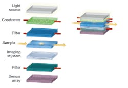
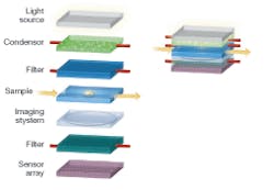
A classic biomedical imaging tool, the conventional microscope, for instance, provides a vehicle for applying optofluidic technology to create a compact and low-cost version of the microscope (see Fig. 1). A conventional microscope contains many optical elements-light source, condenser, spectral filters, sample, and imaging system-and therefore serves as a good illustrative example.
The light source for the microscope can be an array of LEDs embedded in polydimethylsioxane (PDMS) or other transparent material used as the fluidic channel. The LEDs can be placed in the liquid monomer solution and a solid structure is formed when the PDMS containing the LEDs is cured. In some applications, such as two-photon sensing, spectral imaging, or confocal microscopy, a narrowband laser source is needed. A dye laser can be integrated directly into the microfluidic platform. Several such lasers have been demonstrated recently and they generally utilize a microfluidic channel to deliver the dye into the laser microcavity (see Fig. 2). Periodic structures have been used to form distributed-feedback dye lasers in microfluidics that are very narrowband and tunable throughout the visible spectrum.2
The primary function of a condenser in a conventional microscope is to convert the input light field into a uniform illumination on the sample. In addition, a good condenser should ensure that the illumination field impinges upon any given point on the sample from a wide range of angles. A condenser should also be adjustable in terms of its illumination-field area.
These functions can be addressed with a microfluidic-based controllable optical diffuser. Injecting a solution containing scattering particles, such as intralipid or latex microspheres, into a clear microfluidic reservoir, creates such an optical diffuser. The characteristics of the diffuser can be altered by adjusting the concentration of the scattering medium and the choice of scatterers. For example, to achieve a smaller illumination-field area, larger latex microspheres can be used in place of smaller ones; these spheres will scatter preferentially in the forward direction.
Another way to create an optofluidic diffuser is to generate foam (or bubbles) in the microfluidic reservoir. Microfluidics technology can achieve very fine control of the foam-generation process.3 This method is very appealing because it does not require input of any particulate species-it generates and tailors the size of the necessary particles through the combination of air and fluid.
Filtering and sample delivery
Spectral filters are used widely in microscopy. For example, in fluorescence microscopy filters separate the pump wavelength from the emission spectrum. Tunable filters allow visualization of different emission bands or selection of different pumping wavelengths. A tunable filter is implemented in microfluidics by simply inserting a thin layer of an absorbing liquid in the optical path. Such an optofluidic filter can be tuned by substituting a liquid with the proper absorption spectrum. Tunable optofluidic filters can also be realized by a structure consisting of multiple dielectric layers with voids between the layers. A liquid is used to fill the voids and the resulting structure behaves as a multilayer thin-film filter. The filter is tuned by pumping liquids with different indices of refraction in the voids. Continuous tuning is possible, because the index of the fluid can be selected by the mixing ratio of two different liquids.
Sample delivery by microfluidics to the microscope’s field of view is straightforward. Sample manipulation is an easily added function that can be achieved through several well developed optofluidic or microfluidic approaches.
Electro-osmotic (or electrokinetic)-based flow control can be used to move the target sample at different flow rates across the field of view.4 The method simply requires the setup of an electric field along the microfluidic channel. The application of dielectrophoresis-the electrical equivalent of optical tweezing-along the vertical axis can be used to move the target object through the focal plane of the microscope during imaging.5 This method can be implemented by patterning a series of optically transparent electric contacts on the microfluidic channel floor and ceiling with methods such as indium tin oxide (ITO) deposition. In addition, the application of an optical tweezing field can also be used to move and manipulate the target object.
From a system point of view, using microfluidics for sample delivery and manipulation brings numerous other advantages. For example, nourishment and waste disposal can be incorporated in microfluidic systems to sustain the target biological entity during very long timeline experiments. High-throughput screening systems can also be built based on such a microscope design. Objects of interest can be shunted, isolated, and reimaged in real time during the screening process.
Imaging system
The relay and magnification of the transmitted image onto the sensor array can be performed through the use of optofluidic lenses. The proximity of the sample to the sensor array can dramatically simplify the imaging process-there is no need to collimate and relay the light rays to an imaging plane that can be decimeters away. In principle, a single properly designed lens can collect the transmitted light rays from the sample and reconstitute a magnified image onto the sensor array.
The use of optofluidics in the context of lenses is especially appropriate in view of the fact that the optical smoothness of fluid interfaces can be a useful and cost-effective way to circumvent the challenges of creating solid surfaces of similar quality. More important, the meniscus between two immiscible fluids of equal density in a column is perfectly spherical-a curvature profile used in the vast majority of commercially available lenses.
This characteristic has lead to the development of a variable-focus liquid lens by Philips Research Eindhoven (The Netherlands).6 The lens consists of two immiscible liquids of different refractive indices emplaced in a cylindrical housing. The lens is designed such that the curvature of the meniscus and thus the effective focal length of the lens can be altered by electrowetting-a method by which the contact angle of a fluid at the container’s surface can be altered by an electric field (see Fig. 3). The use of a variable-focus optofluidic lens in the microscope allows the user to focus and image different cross sections of the target sample.
Another approach for creating an optofluidic imaging system is to design and fabricate a void into the microfluidic substrate. The effective focal length of the lens can be adjusted by injecting fluid of different refractive index into the void.
Through the use of either electrowetting or changing the lens’ refractive index, such an imaging system promises to be cheaper to fabricate and more compact in implementation.
The field is wide open
These examples illustrate the great potential of optofluidics for achieving integration in biophotonic applications. We have only briefly touched on several emergent optofluidic technologies. An extensive range of highly novel optofluidic technology has been developed in recent years, including methods for creating highly reconfigurable optical waveguides and beamsplitters with fluids, highly sensitive optofluidic molecular sensors based on very high-finesse microtoroids, and optofluidic switches. These existing technologies and those that are just over the horizon constitute a suite of tools that will enable the incorporation of optics and microfluidics to build new and improved biophotonic devices.
REFERENCES
1. A.Y. Fu, C. Spence, A. Scherer, F.H. Arnold, S.R. Quake, Nature Biotechnology 17(11) 1109 (1999).
2. Z.Y.Li, Z.Y. Zhang, T. Emery, A. Scherer, . Psaltis, Optics Express 14(2): 696 (2006).
3. A.M. Ganan-Calvo, J.M.Gordillo, Physical Rev. Lett., 87, 274501 (2001).
4. H.A. Stone, A.D. Stroock, A. Ajdari, Annual Review Fluid Mechanics 36, 381 (2004).
5. M. Durr, J. Kentsch, T. Muller, T. Schnelle, M. Stelzle, Electrophoresis 24(4) 722 (2003).
6. S. Kuiper, B.H.W. Hendriks, Appl. Physics Lett., 85(7) 1128 (2004).
CHANGHUEI YANG is an assistant professor and DEMETRI PSALTIS is the Thomas G. Myers Professor in the Electrical Engineering Department and Bioengineering Department, 13 Moore, Caltech, 1200 E. California Blvd, MC136-93, Pasadena, CA 91125; e-mail: [email protected]; www.optofluidics.caltech.edu/.
Devices abound in nascent discipline
Although optofluidics is a relatively new field, examples of optofluidic devices abound. The liquid-core liquid-cladding waveguide developed by the George Whitesides group at Harvard University (Cambridge, MA) is an excellent example.1 Other examples include optofluidic dye lasers, the optofluidic switch, and the electrowetting-based lens. Rapid advances in optofluidics can be largely attributed to the development of microfluidics and in particular soft-lithography fabrication technology.2 The materials used are generally optically transparent. The soft-lithography process involves fabricating a mask, pouring liquid plastic, such as polydimethylsioxane (PDMS) over the mask, fixing the plastic by baking, and peeling off the flexible end result.3 The start-up cost of a soft-lithography facility is modest (less than $100,000), and the turnaround time from system design to finished prototype can be less than three days. Microfluidic systems can also be contracted and fabricated via the microfluidics foundries created by Stephen Quake at Caltech (kni.caltech.edu/foundry) and Stanford University (Palo Alto, CA).
ACKNOWLEDGMENT
Funding for this research was provided by DARPA Center for Optofluidic Integration.
REFERENCES
1. D.B.Wolfe et al., Proc. National Academy of Sciences of the United States of America 101, 12434 (2004).
2. Y.N. Xia, G.M. Whitesides, Ann. Rev. Materials Science 28, 153 (1998).
3. J.C. McDonald, G.M. Whitesides, Acc. Chem. Res. 35(7) 491 (2002).


