SWIR camera and adaptive optics boost high-speed FSO communications
Information is commonly sent from one point to another through some form of solid cable; examples include corded phones and, via Ethernet, computers. However, physical connections (cable, wire, fiber) may sometimes be impractical or too expensive. In these cases, being able to transmit data through “free space” (air, outer space, and vacuum) is crucial. The use of light to transmit data through free-space optical (FSO) communications overcomes the major drawbacks of cable-based communications.
FSO communication systems
An FSO system in its simplest form is illustrated in Figure 1. Data to be transmitted is converted to a binary format (1 and 0), and then into light pulses (ON/OFF). A transmitter (laser source and focusing lens) sends the light pulses, aiming in the direction of a receiver. The receiver collects the light pulses, which are then processed and converted. Note that the system can be used in the reverse direction. The system interfaces at both ends with a physical network (cable, fiber). In more-complex implementations, the laser beam can be modulated.
FSO can be used for ground-to-ground communication, with examples including outdoor wireless 2G/3G and 4G networks, systems that cover the boundaries of physical networks (“the last mile access”), CCTV surveillance networks, and so on. More importantly, it can be used for ground-to-space (satellite) communications. FSO enables simultaneously establishing a large number of independent links with high throughput; two major advantages compared to radio communications, which has a bandwidth limited by low directionality and radio-frequency throughput (<40 GHz). For example, Earth-observation satellites only overpass ground stations for a couple of minutes per day; it is critical that the large amount of data they collect can be transmitted in a short amount of time, and even more so for military satellites that often may only communicate with ground stations within a limited geographical zone. Finally, FSO is the best option for extraterrestrial communication, which could possibly come into use in the next decades. In short, FSO is a fast-growing segment for telecommunications, both in civil and military fields.
SWIR boosts free-space optics
FSO communications are limited by a series of factors. Fortunately, some can be overcome by using shortwave-infrared (SWIR; 900–1700 nm) rather than visible (400–700 nm) or near-infrared (near-IR; 700–900 nm) wavelengths.
Disturbances inherent to air/free space can influence the optical transmission in several ways: via weather conditions such as fog, rain, or snow; various other effects such as water/dust absorption, scintillation, and scattering; and physical obstructions such as trees, birds, buildings, and so on. These factors attenuate the transmitted signal, leading to a higher number of errors when detecting the signal. Increasing laser power is not the solution, as the laser power density is limited to class 1M to maintain an eye-safe environment.
The use of SWIR-band lasers is extremely pertinent because of the ability of SWIR to penetrate obstacles such as fog and some types of plastics. The recent rise of eye-safe lasers in the SWIR band has helped to enable this technology. However, a camera based on an indium gallium arsenide (InGaAs) detector array must be used at the receiver end, as visible cameras are not sensitive to SWIR wavelengths.
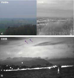
Figure 2 illustrates the advantage of using SWIR cameras in earth-to-earth and earth-to-space configurations. Visibility is increased compared to visible-range imaging, demonstrating how SWIR signal propagates efficiently through the atmosphere.
Adaptive optics in the SWIR range
Light propagating through the atmosphere is typically disturbed by atmospheric turbulence. The most difficult-to-deal-with problem is beam scintillation: as the atmosphere in the beam path fluctuates, the optical power, wavefront tilt, etc. of the light beam vary, causing random phase aberrations and often large variations in detected intensity.
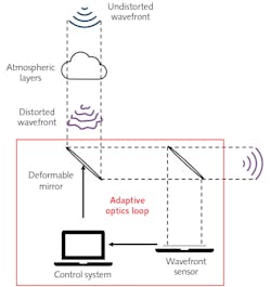
Several mitigation strategies have been developed, but the best way to suppress scintillation is to use adaptive optics (AO). The idea of correcting the atmospheric turbulence in real time for astronomy was first introduced by Horace W. Babcock as early as 1953.1 Enabled by advances in wavefront sensors, deformable mirrors, and real time computers, AO systems have become very popular and relatively straightforward to make. Figure 3 illustrates the working principle of the closed-loop AO approach.
The key parameter of an AO system is the wavefront sensor and its ability to give an instantaneous picture of the incoming wavefront. A wavefront sensor typically consists of a Shack-Hartmann array combined to a photon sensor. First Light Imaging (Meyreuil, France) worked with multiple research institutions on improvements of visible cameras for wavefront sensing and has commercially introduced the OCAM2, which is to date the fastest and lowest-noise (visible photon counting) camera tailored for this purpose.2
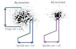
As previously noted, there has been real interest in shifting to SWIR wavelengths for FSO communications. To optimize data-transmission speed, small diodes are used as receivers. To reduce power losses and enable injection of the transmitted optical beam into a single-mode fiber on the receiving end,3 AO is mandatory (see Fig. 4).The major constraint on a camera used as an AO wavefront sensor is that it must provide a real-time snapshot of the wavefront to enable real-time compensation, so the camera should have a high frame rate, low latency, and high sensitivity. For example, very high frame-rate correction is required to perform FSO with low earth orbit (LEO) satellites, where the apparent wind is high due to the satellite’s speed relative to the Earth. The C-RED 3 640 × 512 pixel SWIR camera has been designed specifically for this purpose4 and addresses the challenges of high-speed wavefront sensing.
C-RED 3 camera characteristics
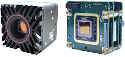
Designed by astronomers for astronomers and benefiting from the expertise gained when designing the OCAM2 and C-RED One cameras, First Light Imaging’s C-RED 3 camera is made in both housed and OEM formats (see Fig. 5). The cooling system has been removed and the electronics squeezed to produce a compact, high-speed SWIR camera. The dark current, which is necessarily high for a nonregulated camera, is compensated by a high frame rate; when used in windowing “region of interest” (ROI) mode at higher frame rates (up to 32,066 fps for smaller ROI vs. 600 fps full-frame), the dark current is negligible. This is especially useful in FSO applications where a limited number of modes will be corrected.
To compensate the effects of temperature and exposure time variations on the dark frame, C-RED 3 has on-the-fly adaptive bias/dark correction to eliminate the need to perform multiple experimental bias/dark acquisitions. Other high-speed characteristics include an electronic shutter with integration pulses shorter than 5 µs in full-frame mode and low camera latency (the delay between end of integration and the first valid data on camera link in normal readout mode full frame is 22.2 µs default and can be tuned down to 7.4 µs).
With improved atmospheric penetration of SWIR lasers in bad weather conditions in comparison to visible-range lasers, along with reduced effects of atmospheric turbulence, there is a real benefit of performing FSO in the SWIR range; AO, paired with sensitive high-frame-rate SWIR cameras, can further optimize the signal detection.
REFERENCES
1. H. W. Babcock, Publ. Astron. Soc. Pac., 65, 386, 229–236 (1953).
2. P. Feautrier et al., Proc. SPIE, 7736, 77360Z (2010); https://doi.org/10.1117/12.856401.
3. S. Muehlbrandt et al., Optica, 3, 7, 741 (2016); https://doi.org/10.1364/optica.3.000741.
4. J.-L. Gach et al., Proc. SPIE, 11272, 112720F (2020); https://doi.org/10.1117/12.2545823.
About the Author
Isaure de Kernier
Applications Scientist, First Light Imaging
Dr. Isaure de Kernier is applications scientist at First Light Imaging (Meyreuil, France).


