Imaging Optics: Freeform and planar phase elements combine for better imaging optics
TONG YANG, DEWEN CHENG, and YONGTIAN WANG
From large space telescopes for observing distant stars, to microscopes used for imaging tiny cells and smartphone cameras recording everyday moments, to head-mounted-display systems used for virtual and augmented reality (VR and AR), imaging optics play a very important role in industry, education, and entertainment.
Continuing advances in science and technology as well as consumer applications are expanding the requirements for modern imaging systems, such as larger fields of view, wider spectral bands, larger apertures, smaller physical volumes, fewer elements, lighter weight, and more complex configurations. Traditional imaging systems using conventional and aspheric optics are falling short of achieving these goals.
Freeform-only and planar-only drawbacks
One trend to fulfill these requirements is the use of freeform surfaces in optical design. With no rotational symmetry and offering high degrees of design freedom, freeform optical surfaces have been successfully applied in many applications such as high-performance head-mounted displays and reflective systems. In short, the use of freeform optical surfaces is seen as a revolution in the optical design field.1
Unfortunately, the use of geometric freeform surfaces may lead to bulky lenses or mirrors and difficulties in system assembly.
Another trend in optical design is the use of phase elements that control the light rays in a different manner. Among them are flat phase elements (meaning that phase functions are applied onto a planar substrate) that are designed to be ultrathin and lightweight. The planar geometry simplifies assembly of the optical system. Typical flat phase elements include diffractive optical elements (DOEs) and metasurfaces.
While freeform- or planar-only elements have individual strengths and weaknesses, a combination of freeform surfaces and flat phase elements in optical design can bring tremendous advantages in the realization of integrated high-performance, compact, lightweight, and easily aligned optical imaging systems.
Freeform + planar
The design of an imaging system combining freeform surfaces and flat phase elements should fulfill the following requirements: First, actual imaging optics work for a certain imaging area and a certain light beam width. So, the light rays from multiple fields and different pupil coordinates should be used during the design. Second, the design method should work for the generation of multiple freeform surfaces and/or planar phase elements in the system. Third, the design should encompass systems with highly nonsymmetric configurations.
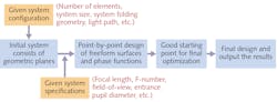
Based on the above three requirements, the School of Optics and Photonics at Beijing Institute of Technology has proposed a point-by-point design method of imaging systems combining freeform surfaces and planar phase elements. This method can be applied to important imaging systems for VR and AR, miniature cameras, high-performance telescopes and microscopes, and illumination optics (see Fig. 1).
Point-by-point design
Traditionally, the design of imaging systems begins from an existing starting point that has similar system specifications and configuration as the design requirements. Then, further optimization is applied to obtain the final result.
However, when designing systems with advanced system parameters and a novel nonsymmetric structure—especially for systems combining freeform surfaces and flat phase elements—it is almost impossible to find proper starting points from existing patents or other available systems. This may lead to a long design process or even failure.
In our proposed method, the whole design process starts from a system with simple and pure geometric planes.2 The planes should be approximately located at their intended positions, and approximately realize the desired light path. Then, the discrete feature rays are sampled from the entire aperture and the full field of view.
The goal of the design process is to redirect the light rays to their ideal image points on the image plane. The freeform surfaces and flat phase elements are constructed by using the feature data points on these elements that correspond with these light rays, which is different from the traditional design method that is based on coefficient optimization.
The freeform surfaces and flat phase elements in the system are generated sequentially. When constructing each element, all the other freeform surfaces or flat phase elements are fixed at their current states. For freeform surface construction, existing methods such as the point-by-point construction-iteration method or other direct design methods can be used.3
Next, the coordinates and surface normals of data points in the real three-dimensional (3D) space (R3S) where the rays intersect with the unknown freeform surface can be calculated and the freeform surface can be generated by surface fitting (see Fig. 2).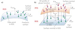
The difficulty here is the fast point-by-point design of the flat phase element, or to be specific, the phase function applied to the phase element. In fact, the graph or profile of the phase function can be viewed as a 3D surface in a virtual 3D space called the “phase function space (PFS).” Essentially, the data points in the PFS corresponding to the intersections of the rays with the flat phase element in R3S can be calculated, thus realizing the phase function construction.
Ray-tracing fundamentals
For the data point calculations, the designer needs to focus on fundamental ray tracing on the phase element. For a feature ray R intersecting at point P on the phase element in the R3S, it follows the general refractive/reflective equation: n’(N×r’)=n(N×r)+N×T∇f(P)ml/2p, where m is diffraction order, l is the wavelength, n and n’ are the refractive indices preceding and following the phase surface, N is the global unit surface normal at P in the R3S and it is uniform on the phase element, ∇f (P) is the gradient vector of the phase function at P, T is a coordinate system transformation matrix, “×” is the cross product, and r is the unit incident direction vector at P, which can be determined by ray tracing when P is fixed.
When the ideal image point for ray R is also fixed, the unit outgoing direction vector r’ can also be determined, since Fermat’s principle indicates that rays of light traverse the path of the stationary optical length with respect to variations of the path. In this way, ∂f(P)=[∂f/∂x, ∂f/∂y, 0] and thus the surface normal [∂f/∂x, ∂f/∂y, -1] can be determined, as well as the tangent plane for the project point Q in the PFS corresponding to point P.
For each unknown phase element, the designer first finds the intersection of the first feature ray with the phase element in R3S. Then, a phase value is assigned for its projected data point in the PFS, allowing calculation of the PFS surface normal. After obtaining the ith data point in the PFS, the (i+1)th data point should be the nearest point to the “point cloud” consisting of the i data points in the PFS.
To be specific, the (i+1)th data point in the PFS is on the tangent plane of the nearest data point among the i data points in the PFS that has already been calculated.4 Using this principle, all the data points with their surface normal in the PFS can be obtained and the closed-form phase function can be generated through a fitting process. These steps can be repeated to obtain all the unknown phase functions.
For the point-by-point design of the freeform surface and flat phase function, there is generally no solution in which the freeform surface or the phase function passes all the data points in the R3S or PFS, and the surface normals after fitting match the results of the original calculation well. It seems that the design goal for the light rays’ redirection to their ideal image points cannot be realized.
However, this goal can be approximately achieved by constructing multiple freeform surfaces and/or phase elements in the system. In addition, an iterative process can be applied here to regenerate the freeform surfaces and the phase functions to improve the imaging performance.
An iterative process
In each iteration step, the freeform surfaces or the phase profiles are regenerated one by one. The intersections of the rays with the freeform surface in the R3S or the projected points in the PFS for the intersections with the phase elements can be obtained. The surface normals in the R3S or PFS are recalculated and the new freeform surface or phase function can be regenerated to replace the previous one.
This iterative step can be repeated and the design output is taken as a good starting point for a very quick final optimization. To summarize, a good starting point for easy optimization is created directly using the proposed point-by-point process based on the design requirements. The dependence on existing starting points is significantly reduced and advanced design skills are not required.
As an example, the proposed method was applied to the design of a compact nonsymmetric reflective imaging system. The entrance pupil diameter is 53 mm and the FOV is 8° × 6°. The F-number of the system is 1.798 and the working wavelength is 1.06 µm.
The primary and tertiary mirrors are flat phase elements, and they are in fact integrated on one substrate; that is, the two different phase functions are applied onto different areas of this single flat phase element, reducing the degrees of freedom for the system assembly by six. The flat nature also contributes to a simplification of the assembly and the secondary mirror is a freeform surface.
We first establish an initial system consisting of only geometric planes (see Fig. 3). After the point-by-point design process, the light rays are approximately redirected to their image points in the second step, resulting in a system that acts as a good starting point for the final optimization, which is achieved in the third and final design step. For this example, the modulation transfer function curves are all higher than 0.5 at 100 line pairs per millimeter for all the fields.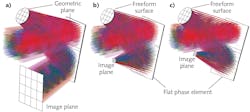
This proposed design method can be integrated into optical design software for broader use by engineers. In addition, future research will focus on the design of systems with curved or freeform-surface-based phase elements that will form the next generation of optical imaging systems.
ACKNOWLEDGMENTS
This work is supported by the National Key R&D Program of China (2017YFA0701200), the National Natural Science Foundation of China (61805012), and the Beijing Institute of Technology Research Fund Program for Young Scholars. We thank Synopsys for the educational license of CODE V software.
REFERENCES
1. K. P. Thompson and J. P. Rolland, Optics & Photonics News, 23, 6, 30–35 (2012).
2. T. Yang, D. Cheng, and Y. Wang, OSA’s Optical Design and Fabrication 2019 (Freeform, OFT), Washington, DC, FM2B.5 (Jun. 2019).
3. T. Yang et al., Opt. Express, 23, 10233–10246 (2015).
4. T. Yang, D. Cheng, and Y. Wang, Opt. Express, 26, 25347–25363 (2018).
Tong Yang is an assistant professor and Dewen Cheng and Yongtian Wang are professors, all in the School of Optics and Photonics at Beijing Institute of Technology, Beijing, China; e-mail: [email protected]; http://english.bit.edu.cn/ensite/optoelectronic/index.htm.