Thin-film-based optical cavity coupling enhances broadband thermal emission
Blackbody and broadband thermal radiation sources are crucial for scientific applications, including thermal sensing, spectroscopy, and energy generation/transfer. Although the thermal radiation of thin-film-emitter-based sources can be enhanced by photonic-crystal cavities, plasmonic antennas, or metamaterial-based microstructures, the enhancement is typically narrowband rather than the more highly desired broadband emission.
An alternative optical-cavity design from researchers at Columbia University (New York, NY), Stanford University (Stanford, CA), the University of Ottawa (Ottawa, ON, Canada), Universidade Estadual de Campinas (Campinas, Brazil), and Instituto de Física da Universidade de São Paulo (São Paulo, Brazil), however, provides broadband enhancement for a thin-film thermal radiation source over a broad wavelength range.1
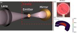
The macroscopic optical cavity consists of a thin-film weak thermal emitter coupled to a mirror to enhance the interaction of thermal light with the emitter. The cavity specifications are optimized to maximize the effective absorptivity and, in turn, effective emissivity according to Kirchhoff’s law (emissivity = absorption = 1 – reflectivity – transmittivity).
Cavity coupling optimization
The secret to achieving both high emissivity and broadband thermal output is appropriate selection of the thin-film emitter and optical mirror. The demonstration uses microcrystalline silicon carbide (µC-SiC) thin film that serves as both a weak thermal emitter (with weak absorption in the mid-infrared spectrum) and as a partial reflector to complement the high-reflectivity broadband metallic mirror that completes the cavity.
The maximum enhancement in thermal output is predicted when the intrinsic losses of the system (thermal emitter and metallic mirrors) are optimally matched to the transmission of the cavity. The absorption losses from the thermal emitter can be modified through appropriate choice of film thickness. The µC-SiC thin film was chosen not only for its weak mid-infrared absorption, but also for its compatibility with silicon process technology and ability to withstand high temperatures.
The circularly patterned (800 µm) suspended silicon carbide thin-film membrane emitters with an optimized film thickness of 100 nm are prepared on a silicon wafer. The suspended membrane emitters have significantly small thermal mass compared to bulk emitters. These thin-film emitters require lower heating powers, but are also inherently dim when hot (see figure).
The suspended emitters are configured in the experimental setup and optically aligned to a metallic concave mirror to form a cavity. The thin-film µC-SiC is heated to a temperature of approximately 580 K using integrated platinum heaters and the spectral emission from the coupled system is collected using a lens and directed through a spectrometer to measure its spectral power distribution. Power emission up to twofold over that from the bare emitter can be due to the presence of the mirror. However, any emission power more than twofold is a clear indication of enhanced thermal emission.
The emitter-coupled-cavity system shows more than threefold enhancement in emission power over the 3.0–3.4 µm wavelength range as compared to the thin-film SiC emitter without a cavity (bare emitter). The integrated power enhancement over the entire 2–4.2 µm wavelength range is also found to be more than twofold. The temperature of the membrane emitter remains constant during the entire spectral measurement.
“We can enhance the spectral power distribution of thermal emission up to blackbody by just appropriate design of cavity parameters and irrespective of the emitter material; moreover, the performance of optical elements remains unaffected by the emitter temperature since they are physically detached from thermal element,” says Gaurang Bhatt, a graduate student in the Department of Electrical Engineering at Columbia University.
REFERENCE
1. G. R. Bhatt et al., Opt. Express, 27, 12, A818–A828 (2019).
About the Author

Gail Overton
Senior Editor (2004-2020)
Gail has more than 30 years of engineering, marketing, product management, and editorial experience in the photonics and optical communications industry. Before joining the staff at Laser Focus World in 2004, she held many product management and product marketing roles in the fiber-optics industry, most notably at Hughes (El Segundo, CA), GTE Labs (Waltham, MA), Corning (Corning, NY), Photon Kinetics (Beaverton, OR), and Newport Corporation (Irvine, CA). During her marketing career, Gail published articles in WDM Solutions and Sensors magazine and traveled internationally to conduct product and sales training. Gail received her BS degree in physics, with an emphasis in optics, from San Diego State University in San Diego, CA in May 1986.