LASER-SYSTEM DESIGN: Dedicated electronic pods simplify laser synchronization
STEVEN KAN
Laser physicists and engineers frequently require synchronization of various components in their laser systems for experimentation, test, or system integration. While turnkey laser systems may have fully integrated timing, systems built from separate components leave the electronics burden to the user. When the timing linkages between two system components are electrical rather than optical, many laser physicists and engineers find themselves in unfamiliar territory. Even when suitable electrical-engineering resources are available, the build-versus-buy equation often favors off-the-shelf solutions, especially when time to market is considered.
Typical laser-synchronization tasks include frequency division (synchronization of high-frequency events with lower-frequency ones); pulse conversion (triggering of logic circuits from sine-wave sources or weak signals); and trigger fanout (triggering multiple inputs from a single timing source).
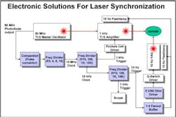
A lab experiment or system-integration project might involve one, some, or all of the above simultaneously (see Fig. 1). There are many possible solutions for this general category of problems. These include building custom circuits for frequency division, pulse generation/buffering, or trigger fanout; using computer-based digital input/output (I/O) cards for countdown triggering or fanout; using programmable pulse-pattern generators or delay generators for pulse countdown and fanout; or buying inexpensive signal-buffering and translation pods.
Building a custom circuit is desirable for some laser applications, as the end user can specify features, constraints, and costs. But designing custom circuitry takes time, and high-speed electronics engineering can be as demanding as the laser engineering itself. Even when suitable ICs (integrated circuits) or field-programmable gate arrays are available to provide the required functions, there is additional design work required to implement supporting circuitry, supply power, create suitable I/O interfaces, and so on. Circuit-board layout is another nontrivial task, especially when the application requires high frequencies, short pulse lengths, low jitter, or all of the above.
Computer-based digital I/O cards can be used to shorten the design cycle, but they may still require engineering to get appropriate signal levels into and out of the computer. For example, many digital I/O cards, even those with programmable output levels, will not drive 50-ohm loads—a requirement for transmitting high-speed signals across any appreciable cable distance. They may also require software development. Furthermore, many computer-based solutions will run at rates only up to a few tens of megahertz, whereas many modern laser applications require working well into the gigahertz regime.
The off-the-shelf approach
Programmable pulse generators and delay generators can solve many of these problems. They are typically easier to use than plug-in cards, they are designed to interface with other instrumentation, and they are often available with high operating frequencies. Their major obstacle is cost. A typical delay generator can cost $5,000 to $6,000 depending on options, and a high-frequency-pulse pattern generator can easily cost $20,000 to $50,000 or more. Such powerful instruments are clearly overkill for simple tasks like frequency division, signal buffering, or fanout.
A common problem with both the digital I/O and pulse-generator approaches is that their size and complexity preclude them from being viable solutions for OEM and system-integration applications. While it might be appropriate to add yet another personal computer (PC) to an experimental lab setup, integrating a PC, plug-in card, or benchtop instrument to a production test system or shipping product may be undesirable or infeasible.
Recently, an increasing number of laser engineers have turned to off-the-shelf signal-buffering and translation pods to perform laser synchronization functions. While these modules provide instrument-level performance, each performs only a specific function, so they are lower in cost ($350 to $1,200). They are also compact (1.25 x 3 x 3 to 6 in., without the AC adapter), making them competitive in size with a custom circuit board. Rugged enclosures and standard connectors allow them to be integrated quickly into experimental labs, production test systems, or OEM products with no engineering required. When compared with the relative cost and availability of such off-the-shelf solutions, the cost "savings" of designing a custom circuit quickly disappear, especially when time to market is considered.
Frequency division
One very common application is the requirement to synchronize the repetition rate of a laser oscillator with lower-repetition-rate system components such as laser amplifiers, xenon flash lamps, Q-switch drivers, or Pockels-cell drivers operating in the kilohertz or hertz range. Such frequency division (or "pulse-skipping") is commonly performed using programmable-delay generators. A reference clock is used to trigger the input to the delay generator, and the output pulse is emitted some programmed time later, after which the cycle repeats. Multiple delay generators can then be deployed in serial or parallel fashion to create the various frequencies required throughout the system.
Many delay generators use an internal timebase, which decouples them from the input signal, so the phase relationship between the reference clock and the output pulse is not deterministic. Furthermore, popular delay generators have a jitter floor of 50 ps in the best case, with the jitter rising as a function of programmed delay. While jitter and phase alignment may not be important for flashlamp timing, they are critical for triggering of Pockels cells or pulsing of accelerator photocathodes.
This problem can be partially solved by implementing a circuit to use the delay generator output as an "arm" or gate to control pass-through of the original reference signal that then triggers the target, but the two timebases are still asynchronous. Jack Sankey, who works in ultrafast-pulse generation at Cornell University (Ithaca, NY), observed that the asynchronous arm/trigger approach can create "a problem (that occurs more often than one might expect) when it arms at the same time the trigger edge arrives, and enormous jitter ensues." These problems can be solved with additional retiming circuitry, but this adds additional complexity.
Gunter Steinmeyer, a researcher at the Max-Born-Institute for Nonlinear Optics and Short Pulse Spectroscopy (Berlin, Germany) concurs. "This philosophy in trigger generation has completely changed since people have started to stabilize the carrier-envelope offset frequency of their oscillators," he notes. "Now you do not get away with the awkward trigger-and-wait circuitry."
Edge-triggered frequency dividers
These jitter and phase demands often make it desirable to derive all system timing from one master clock. Synchronization tasks like these can be solved using a variety of dedicated frequency divider modules. For example, a programmable frequency divider produced by Pulse Research Lab operates from DC to 1.25 GHz and can accept a variety of input signal types, such as TTL, ECL, or AC-coupled sine waves (200 mV peak-to-peak minimum). The division ratios are programmable from f/2 to f/4096. Other versions operate up to 12 GHz or with ratios up to f/10,000; units can be cascaded to generate division ratios into the millions or billions.
Because these frequency dividers are edge-triggered, they are inherently locked to the timebase of the input signal, and can operate over a very wide frequency range. If an oscillator frequency changes either due to piezoelectric microadjustment or gross cavity length adjustment, the divided frequency ratio and phase relationship between input and output remain constant. These dividers can also be reprogrammed for different division ratios and repurposed for different applications at different operating frequencies. By contrast, analog frequency-synthesis techniques are typically tuned for a specific, narrow band of frequencies. Furthermore, analog frequency synthesis has an unavoidable link between frequency and slew rate, which makes it difficult to create low-frequency events with low jitter. A phase-locked loop to lock two signals over seven orders of magnitude in frequency would be very difficult to implement with low jitter, whereas it is relatively simple to divide by 8 million using counter-based circuits.
One frequency divider produced by Pulse Research Lab (the PRL-260ANT) typically tests less than 5 ps root-mean-square total jitter, including clock and trigger jitter (see Fig. 2). Currently, we do not have test data separating the various components of jitter for this device but independent testing of a similar model has shown one-sigma random jitter of less than 1 ps when dividing a 2.125 GHz clock source by 8.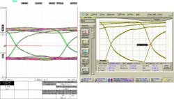
Other fixed- and programmable-ratio frequency-divider modules include emitter-coupled-logic modules operating up to 3 GHz and current-mode-logic input modules operating up to 12 GHz. This spans popular particle-accelerator frequencies (for example, 11.424 GHz X-band and 2.856 GHz S-band) that must be synced up with laser systems running in the 30 to 120 MHz range.
These frequency dividers have been successfully used for timing of Pockels cells, Q switches, seed lasers, flash-lamps, and so on. Units have been cascaded to produce ratios of up to f/8,000,000, for example to reduce the 80 MHz frequency of a Ti:sapphire oscillator to 10 Hz for synchronization of a YAG pump laser for pump/probe spectroscopy. Simple and inexpensive frequency division makes it easy to implement a network of phase-synchronized clocks.
Converting sine waves and weak signals to drive 50-ohm loads
Another common application is the requirement to trigger a laser or system component from an incompatible timing signal. Frequently, the electrical output from a photodiode or radio-frequency (RF) source does not match the triggering requirements of the next component in the system. A common case is that of an RF sine-wave source mismatched with a TTL trigger input. In these cases, a dual-channel comparator with TTL outputs can be used. The comparator input will trigger on signals as small as 10 mV (into 50 ohm), and the TTL outputs will deliver TTL-compatible signals into 50-ohm loads over long cables.
These comparators can also be used to convert fast-photodiode outputs into usable logic signals. For example, an oscilloscope capture that Continuum (Santa Clara, CA) sent to Pulse Research Lab shows a Ti:sapphire oscillator's photodiode output (see Fig. 3). With only about 25 mV of detectable signal above the noise—far too low to trigger a TTL-, NECL-, or NIM-compatible input—the photodiode output could not be used directly to synchronously trigger the downstream laser amplifier. A set of Pulse Research Labs comparator and frequency-divider modules was used to convert this signal into an ECL trigger signal, which was then used to trigger the second laser (other versions produce PECL- and LVPECL-compatible pulses from small signals).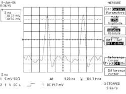
Some laser-system components have external trigger inputs requiring 5 V pulses into a 50-ohm load, which standard TTL circuits will not deliver. For example, several models of Pockels Cell and Q-switch driver modules from Kentech Instruments Ltd. (Didcot, England) require a minimum of 5 V into 50 ohm, as do several streak cameras from Hamamatsu (Hamamatsu City, Japan). Programmable pulse generators can be used to generate these levels, but they are relatively expensive and do not typically have fast rise times at these amplitudes. A variable pulse driver from Pulse Research Labs (the PRL-470B) generates 10 V into open-circuit or 5 V into 50 ohm, and has a less-than 1 ns rise time (5 V peak-to-peak into 50 ohm) that can also be used for directly driving some laser diodes.
Trigger fanout
Another common requirement is the ability to trigger multiple devices in the system from a single trigger or timing source. The downstream devices may be lasers, cameras, data-acquisition systems, or just everyday lab equipment such as oscilloscopes, counters, and logic analyzers. Unlike RF signals, high-speed logic signals cannot be simply split or teed off to multiple destinations; they must be actively buffered when they are fanned out.
If a matched-impedance resistive splitter or power divider is used (as would be appropriate when splitting RF signals), the signal attenuation will render the trigger incompatible with the receiver because most logic input circuits do not have gain.
If a simple "tee" is used, there are two possible failure modes. First, if the loads are high-impedance, signals will be reflected from each load to the other loads, potentially causing spurious triggering. Second, if each load on the tee is terminated with 50 ohm, the resulting resistor-divider circuit creates a net 25-ohm load that will cause unacceptable attenuation.
High-speed trigger buffering must also include 50-ohm back-termination to prevent signal reflection from high-impedance loads from causing spurious triggering. This is true even for low-frequency triggers, as it is the ratio of the signal rise time to the transmission-line propagation time rather than toggle rate that determines the need to match impedance.
Although each application (frequency division, pulse conversion, and trigger fanout) differs in its details, the overall themes are recurrent—there is a widespread need for low-cost electronics to accomplish these tasks with low jitter. Off-the-shelf signal-buffering and translation pods can perform laser-synchronization functions both efficiently and inexpensively, filling this need.
The author wishes to thank Gil Travish of the Particle Beam Physics Laboratory at UCLA (Los Angeles, CA) and Jens Schwarz of the Z-Backlighter facility at Sandia National Laboratory (Albuquerque, NM) for their assistance in writing this article.
Steven Kan is vice president of sales and marketing at Pulse Research Lab, 1234 Francisco St., Torrance, CA 90502; e-mail: [email protected]; www.pulseresearchlab.com.