Sealed CO2 lasers take the modular approach
Carbon dioxide (CO2) lasers have become a mainstay in a wide variety of industrial, medical, and scientific processes. These lasers are often integrated into assembly lines, on movable gantries or on robot arms, with applications ranging from metal cutting and welding, cutting dieboard or complex acrylic signage, to textile processing and package marking. Carbon dioxide lasers can even be found marking date codes on cheese, fruit, or other food products. However, in many respects, advances in laser design have failed to keep pace with the changing requirements that new markets and applications are demanding. Laser manufacturers have to constantly reconcile the demand for low cost, high reliability, and long lifetime with the desire for compact size and maximum performance to meet the needs of new markets.
One design approach is to develop lasers based on modules. Use of a basic core building block allows such lasers to be scalable to higher performance levels while simultaneously taking advantage of manufacturing cost efficiencies. In 1982, Synrad used this approach successfully with its industrial sealed CO2 lasers. With a 10-W laser as the basic unit, this design could be scaled in length and/or optically combined to achieve both 25- and 50-W versions. Twenty years later, Synrad is using a similar approach to develop a range of higher-power lasers based on what it calls “f-technology.”
Scaling and combining units
The original design had laser lifetimes of more than 20,000 hours, and high reliability suitable for round-the-clock industrial processes. Drawing upon this experience-especially with respect to gas chemistry and sealed-tube technology-was essential in the development of a new higher-power laser. In direct analogy, the higher-power lasers have been designed around a 100-W basic unit that lends itself to scaling and combining to produce devices with nominal output powers of 200, 400, and above.
Any industrial-laser design arises from a series of choices and tradeoffs between size, cost, performance, and efficiency. Many decisions are closely related to either how effectively the design allows the removal of excess heat from the laser discharge, or the desire for an optical-resonator design that ensures good optical performance while remaining cost-effective and simple to manufacture in large quantities.
Gas temperature is a critical parameter that influences the beam quality, power level, and overall size of the laser structure. It is well known that the maximum acceptable operating temperature for a CO2 laser plasma is on the order of 600 K. Therefore, with typical drive-power-to-optical-output conversion efficiencies in the range of 10% to 15%, the real challenge is to efficiently remove the excess heat from the plasma region yet avoid making the overall mechanical design too cumbersome or complicated. Some approaches have used fluid-based cooling to directly cool the electrodes, or have resorted to active circulation of the laser gas itself. But, because both of these methods add complexity and expense to the overall system design, passive techniques are preferred at low to moderate power levels (less than 1 kW).
Higher heat transfer
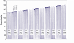
Typically, in a passive approach, some form of additional structure, such as a discharge sidewall, is used to help cool the plasma. However, enclosing the entire active discharge region prevents the hot laser gas from expanding, which provides increased cooling capacity but at the expense of some other performance factor, such as pulsing performance or operational frequency limitations. This design limitation has been overcome at Synrad by the use of alumina ceramic cooling plates as a heat-transfer method between the inner electrodes and outer-tube housing (see Fig. 1). In addition to providing a 2.5-order-of-magnitude increase in thermal conductivity compared to using no ceramic plates, this method enables the hot discharge gas to expand virtually unencumbered. This produces desirable frequency-response characteristics, as well as typical single-pulse and shot-to-shot stability variations of better than ±5 % (see Fig. 2).


