Early diode lasers were jokingly referred to as flashbulbs because their lifetimes were measured in minutes. Some lasers died a quick death from facet damage. Others died more slowly, as defects spread through the diode crystal and caused dark lines to appear in the output. Following the invention of the double heterostructure in 1970, which allowed continuous-wave (CW) room-temperature operation, researchers focused on improving device lifetime.
Optical communications was the application that motivated laser-diode research. Optical fiber in 1970 was still brittle and lossy, but performance was improving rapidly. Reliable diode lasers were highly sought after. By improving the liquid-phase-epitaxy fabrication process, Bell Labs (Murray Hill, NJ) reported thousand-hour device lifetimes in 1973, and in 1975 Diode Laser Labs (NJ) offered the first commercial CW room-temperature devices. Lifetimes were quoted at 10,000 hours.
But somewhat to the surprise of researchers, those devices still fell short of what was required for communication transmitters. Beam pattern, spectrum, and power all varied sharply with temperature, time, and current, while telecom engineers expected the laser output to be stable even when modulated. In addition, there was a growing recognition of the need for lasers operating near the optimum fiber loss and dispersion regions at 1.3 or 1.55 µm, far from the wavelength of the gallium aluminum arsenide (GaAlAs) devices then available.
Fortunately, a different and less-demanding application—the audio compact disk (CD-audio)—could make use of diode lasers with their existing wavelength and power. Its overwhelming success served to provide massive capital investment that underwrote diode-laser development to the benefit of all other applications. These new advances both profited from and added to the growing economic power of “Japan Inc.”
Development goes abroad
Optical storage was one of the first applications envisioned for lasers, and by 1964 RCA had demonstrated a laser-based home video system. Several other companies pursued and then abandoned this market, in part because of the cost of the HeNe laser components, until finally the field was left to Philips (Eindhoven, The Netherlands). By 1980, Philips had partnered with Sony (Tokyo, Japan) to develop a spin-off product, CD-audio using a 780-nm GaAlAs diode laser.
The digital data format of CDs was developed in part to compensate for the lower-quality beam of diode lasers (compared to HeNes), but improvements in diodes were still needed for reliable system performance. Much of this work was done with a measure of secrecy—not unexpected in an industry developing a revolutionary new product.
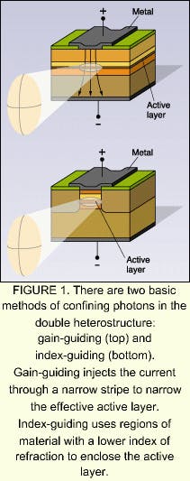
The next major improvement in diode lasers was the invention of index-guiding. In the double heterostructure, photons are confined to the junction region in the vertical direction by total internal reflection. Transverse confinement comes through restricting the gain in this dimension simply by applying the current through a narrow stripe (see Fig. 1). Hence, these devices are called gain-guided lasers.A logical extension of heterostructure photon confinement is to enclose the gain region with vertical walls of material that exhibits a lower refractive index. Such devices are called index-guided lasers. They possess a surprising number of advantages over gain-guided lasers. Proposed and developed by a variety of Japanese and American firms, including Mitsubishi (Tokyo, Japan) in 1972, devices based on this structure proliferated in a bewildering family of acronyms.
A mode in the hand
Gain-guided lasers are inherently multimode, and power and beam parameters depend nonlinearly on current, temperature, and the age of the device. Moreover, the beam appears to diverge in the vertical and transverse directions from two different depths within the diode—that is, the beam is astigmatic.
In contrast, index-guided lasers in CW operation are single-mode, with a linear output that is stable with time and temperature. Perhaps even more significant, the beam is not astigmatic, making index-guided lasers the device of choice for the CD application. Furthermore, confining the photons more tightly resulted in lower threshold and operating currents.
Lowering the operating current contributed significantly to increasing diode lifetime. In addition, continued intensive work on the liquid-phase-epitaxy process had shown that decreasing oxygen contamination during fabrication greatly reduced crystal defects. By 1976, Japanese researchers were extrapolating device lifetimes beyond 1 million hours, and Bell Labs reported similar results in 1977. By the early 1980s, every major Japanese electronics firm was producing “visible” diode lasers (the visible regime for diodes was extended wishfully to 780 nm).
Music that’s miles long
Philips and Sony proposed CD-audio standards in 1982 for format, size, and playing time. (It was said that the 74-minute standard time was set to record Beethoven’s Ninth Symphony, a favorite of Sony chairman Akio Morita.) By the end of the decade, tens of millions of CD players were being sold annually—it was difficult to even find the formerly ubiquitous long-playing records (LPs). CD-audio was even credited with revitalizing the music industry, and Billy Joel’s 52nd Street was the first album produced expressly for the CD format.
At one time, nine large Japanese corporations competed in this market, and the price of diode lasers used in CD players fell to less than $10 by 1985. Eventually, Sharp came to dominate, producing more than 70% of the diode lasers used for optical storage.
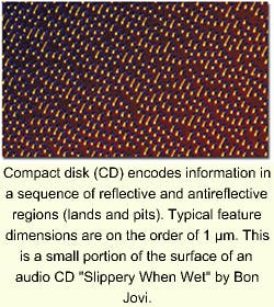
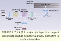
The advantages of CD-audio over LPs and magnetic tape were clear: greater reliability in both the media and read mechanism (the mechanism never touches the media), higher data density, efficient mass production, and better fidelity. CD-audio has a 90-dB dynamic range compared to 70 dB for LPs under the very best circumstances. And because the read beam is focused through a thick protective acrylic layer, small surface defects have little impact on playback accuracy (see Fig. 2).Information on a standard CD is placed in a spiral track 1.6 µm wide and more than 5 km long. The reflective flat surface in the track, the land, is marked by pits of about 1 µm in width. The pit depth of l/4 n (n is the refractive index of the acrylic, so this depth is about 133 nm) is chosen so that light reflected from a pit destructively interferes with the incident beam and modulates the beam reflected from the spinning disk.
The track starts at the center of the CD, and the disk slows from 500 to 200 rpm to maintain a constant scan rate as the read head spirals outward.
How it’s done
The 3-mW output of these GaAlAs diodes provides adequate signal-to-noise ratios but with power low enough to avoid altering the media when focused to a 1-µm spot. Although not astigmatic, the beam is still elliptical and needs to be made circular to achieve a tight focus (see “Correcting diode-laser beams”). Focus must be maintained to within 0.5 µm, and the head must track accurately to at least 0.1 µm.
An astigmatic lens is placed in front of the detector to provide a focusing correction signal. The vertical and horizontal parts of the two elliptical beams produced by the lens on the quad detector will cancel out when reflections from the disk have the same focus.
Tracking is accomplished by forming the pits with sloping walls to reflect light radially inward or outward. The incident laser beam is divided by a diffraction grating to produce the two reflections from the pit walls. These signals are balanced to center the focused beam within the track.
The coherence length of index-guided lasers makes them especially susceptible to instabilities from optical feedback—reflections from the disk re-entering the diode gain region. Feedback can be avoided with a standard isolator made of a polarizer and a quarter-wave plate. The reflected beam is directed to the detector by the polarizing beamsplitter, and the modulations are converted to analog signals that reproduce the music (or data).
Never enough
The success of CD-audio stimulated two further developments. The first was the ongoing effort to overcome the single major disadvantage of optical vs. magnetic media—to make writing data as easy and cost-effective as the read-only operation. The second, extending the audio format to include read-only computer information (CD-ROM), was simpler and yielded more immediate results, comparable in impact on the PC industry to that of CD-audio on the music industry.
CD-ROM per se required no improvements to the laser component. The write operation for CDs, however, did need higher power. Index-guided lasers, by virtue of their smaller spot size, were prone to catastrophic facet damage as output power increased. Passivating the diode prevented oxidation at the facets, and hence improved resistance to facet damagea discovery that had far-reaching benefits for future higher-power applications.
It has proven to be true that the need for information storage expands to fill all available capacity, creating a demand for more storage. The next generation of optical storage, digital video disk (DVD), has about seven times the capacity of CD-ROM and also is diode-laser-based, using shorter wavelength devices that truly are visible. Because the density of stored data is inversely proportional to the square of the wavelength, the demand for shorter-wavelength diode lasers is guaranteed to continue.
Next month this series will discuss the development of visible diode lasers.
Correcting diode-laser beams
Early generations of diode lasers all produced elliptical and highly divergent beams, even when they were not astigmatic. Typical full widths at half maximum might be 50° and 10° for the two perpendicular axes. For engineers used to designing for the high-quality output of HeNe lasers, the first task was to change diode output into a circular, well-collimated beam that could be tightly focused.
To transform the beam from elliptical to circular, an optical system is needed that has different focal lengths along the two axes. A cylindrical lens is the simplest solution and is commonly used in less-demanding applications, but it has the disadvantage of requiring long working distances. A different method uses a pair of prisms, a so-called "wedge prism." This design is compact, flexible, and presents flat surfaces to the beam, minimizing wavefront distortion.
Collimating a highly divergent beam requires a lens with a large numerical aperture; maintaining good wavefront properties (necessary for reading data from optical disks) requires that spherical aberration be kept to a minimum. Shown above is a simple optical system that collimates, circularizes, and focuses a nonastigmatic diode-laser output.
About the Author
Stephen J. Matthews
Contributing Editor
Stephen J. Matthews was a Contributing Editor for Laser Focus World.


