Diode laser simplifies holographic system setup
Diode laser simplifies holographic system setup
Matthias Bohnacker and Bernhard Lau
One of the main applications of pulsed ruby lasers is holographic interferometry of moving objects by means of double pulses with a temporal separation ranging from 1 µs to 1 ms.1 Because the ruby laser produces only three to five pulse pairs per minute, optical alignment of the holographic setup is difficult.
In conventional systems, the beam of a helium neon (HeNe) laser is coupled into the beam path of the pulsed laser and used for both alignment and hologram reconstruction. This approach has a number of drawbacks. It necessitates a complex optical design with tight alignment tolerances and high-loss beam splitters. In case of a change in the optical setup, for example, when a new object is introduced, the alignment path must be altered and the beam realigned.
The HeNe laser operates at 633 nm compared to the 694-nm output of the ruby laser, and the two sources have different beam profiles. Thus, reconstruction of a ruby-laser-generated hologram using a HeNe source will not be identical to the original object wave. Position and magnification of the reconstructed object deviate from the original, and optical aberrations may be introduced.2 Furthermore, unwanted and dangerous reflections of the pulsed laser radiation may not be foreseen during the alignment process when the HeNe laser is used.
The ideal alignment beam would be identical to the beam of the pulsed laser in wavelength, angle of divergence, and position of the beam waist, just as if the pulsed laser was operated in continuous wave (CW) mode. To enable a correct reconstruction of holograms, the wavelength and the beam profile of the pilot beam should coincide with those of the ruby laser beam as exactly as possible.
An alignment system has been made specifically to address these concerns. It involves a collimated diode laser with a wavelength of 690 nm, well matched to the 694-nm output of the ruby laser. The diode source is mounted directly in the housing of the main laser, and the output is directed into the ruby laser beam path by means of an electromagnetically controlled Goulier pentagonal prism.3,4 This diode laser can be used not only for alignment of the holographic beam path and for reconstruction, but also to record holograms.
Technical details of system
The active medium of the ruby laser is chromium oxide-doped sapphire (Cr2O3:Al2O3). The system is a flashlamp pumped, Q-switched Lumonics (Rugby, UK) source that produces 30-ns pulses at 694.3 nm. A spatial filter consisting of a lens and pinhole is installed after the oscillator to improve beam quality. The output is amplified using a second ruby rod, resulting in output pulse energies as high as 2 J with a coherence length of roughly 2 m.
The "equivalent continuous wave laser" used in the alignment/reconstruction system is a Toshiba (Tokyo, Japan) TOLD 9150 indium gallium aluminum phosphide (InGaAlP) diode laser operating at 690 nm with an output power of 30 mW. The elliptical beam profile divergence angles are 18° and 8.5°. Oscillation may occur in one or several longitudinal modes, depending on device junction temperature and operating current, and coherence length can run as high as tens of centimeters.
Alignment system design
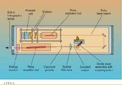
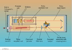
The output beam of the ruby laser goes through a pair of fold mirrors and is focused by the spatial filter lens (see
Fig. 1). The diode laser output is collimated by an aspheric lens and coupled into the ruby laser beam between the second deflecting mirror and the spatial filter. Coupling the beam in at this point offers several advantages. Because both beams hit the lens in parallel and are focused by it, they experience the same amount of divergence. In both cases, the spatial filter pinhole defines the position of the beam waist, yielding nearly identical wavefronts. The pinhole and the amplifier rod clearly define the beam axis, facilitating the alignment of the diode laser.
The diode laser beam is switched in and out of the ruby beam using an electromagnetically controlled Goulier pentagonal prism. A Goulier prism deflects an incident beam by exactly 90°, independent of the angle of incidence. Thus the angular position of the prism is not critical. Alignment of the diode laser beam requires four degrees of freedom, which are realized with simple screws and springs.
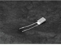
The diode laser is temperature-stabilized by a Peltier thermoelectric cooling element. The diode is thermally and electrically insulated by a glass ceramic housing manufactured in-house.5
Electromagnetic interference protection
The discharge of the flashlamp capacitors in the ruby laser system generates strong electromagnetic waves that threaten the voltage-sensitive diode laser. The flashlamp cabling inductively couples these electromagnetic surges to the diode laser power supply. The mechanical and electrical setup of the alignment source and its power supply must thus be designed to withstand electromagnetic interference.
A number of features have been included in the system that decrease the interference experienced by the diode laser.6 We control the diode laser with an analog current control. The diode laser has a built-in photodiode power monitor that we use to stabilize the output power by regulating the current. An additional current limiter is implemented for safety. To adjust the current, we use a separate display unit that either shows the diode laser or the photodiode current, the latter being a function of output power. This unit must be removed before the ruby laser is switched on.
An interlock prevents the simultaneous operation of the two lasers, preventing voltage transients from reaching the semiconductor laser via its power supply. The circuit layouts are compact, and short shielded leads are used for the diode laser. Ground loops are avoided by star-like grounding, and the diode laser power supply and current control are placed in shielded housings. Finally, residual voltage transients are suppressed by filters.
Power concerns
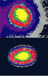
The diode laser beam experiences significant power loss due to optical components. The initial 30-mW output is reduced 9 mW at the exit port of the system. The main losses occur in the diode laser collimator lens (insufficient f-number) and in the ruby rod of the amplifier. In both cases the beam is limited at its larger angle of divergence (see Fig. 2).
Power is also a concern during hologram reconstruction. For this operation, a beamsplitter is used to separate the reference wave from the main beam. Reference beam power is thus only a fraction of the total diode laser output, making the reconstructions very faint and difficult to record with a CCD camera. This could be improved by using a semiconductor laser with a higher output power. However, such lasers are costly and restricted to multimode operation that is unsuitable for hologram recording, though they permit bright reconstructions.
Another solution would be to use a variable beamsplitter plate in the holography setup. The intensity of the reference wave could then be increased when it is used as a reconstruction wave. However this beamsplitter must be able to withstand the high pulse power of the ruby laser. As far as we know, there is at present no such beamsplitter commercially available. Future improvements could include use of an anamorphic collimator to obtain better coincidence of the wave fronts and increased usable beam power.
The diode laser alignment system considerably facilitates the handling of the ruby laser and increases operational safety. The source can also be used for reconstructing or even recording holograms. With its economical construction and simple alignment and operation, a modified version of this system could be applied not only to other pulsed laser systems, but to infrared or ultraviolet-emitting lasers where similar optical alignment problems exist. n
REFERENCES
1. H. Marwitz, ed., Praxis der Holografie, Expert-Verlag, Ehningen, Germany (1990).
2. P. Hariharan, Optical Holography, Cambridge Studies in Modern Optics 2, Cambridge University Press, Cambridge, MA (1984).
3. L. Bergmann and C. Schäfer, Lehrbuch der Experimentalphysik Bergmann/Schäfer, Band 3: Optik, Walter de Gruyter, New York, NY (1978).
4. H. Naumann and G. Schröder, Bauelemente der Optik, Carl Hanser, München, Germany (1993).
5. MACOR glass ceramics, Paul F. Schröder & Co. Spezialglastechnik, Buchenweg 20, D-25479 Ellerau, Germany.
6. A. Weber, EMV in der Praxis, Hüthig-Verlag, Heidelberg, Germany (1994).
FIGURE 1. Alignment laser assembly is built into the ruby laser housing (top) and coupled into the main beam using a coupling prism operated with an electromagnetic switch (bottom).
FIGURE 2. Beam profiles of the ruby laser (top) and the semiconductor laser taken about 40 cm from the ruby laser exit port (bottom) show good agreement. The intensity distribution is color-coded.


