Laser powers lunar rover model
OSAKA-A research team consisting of the Nobuki Kawashima group at Kinki University, Mitsubishi Heavy Industries (Tokyo), and other groups has successfully transferred power from a semiconductor laser to a scale model of a lunar rover 100 m away, allowing remote use of the vehicle. In 1998, NASA launched an unmanned lunar orbital vehicle to explore the polar regions of the moon. Using neutron spectroscopy, it was shown that the polar regions of the moon could possibly have as much as 6 billion tons of water. The existence of water on the moon leads to the possibility of life there.
After the spectroscopic analysis, the lunar prospector sought to detect ice by colliding a probe into a chosen polar region and analyzing the particles flying off because of shock. The presence of ice, however, could not be confirmed. Realizing that these methods to detect the presence of ice on the moon are indirect, the Japanese research team has sought a direct way to directly determine whether ice exists. Obstacles preventing the direct exploration of the polar regions include those caused by the polar regions always being in the shadow: extreme low temperatures and the inability to directly harness solar energy.
The exploration method developed by this team consists of three main parts: relay satellite, mother ship, and rover. The relay satellite mediates communication between the rover and Earth. The mother ship converts solar energy to laser light and controls the rover. The rover explores the surface of the moon using energy transmitted by the mother ship.
This experiment tested the transfer of energy between the mother ship and the rover. Using a 812.3-nm-emiting 34-W semiconductor laser, a scale-model 17-kg rover was controlled from a distance of approximately 100 m. The laser was placed inside an observatory at Kinki University and the model rover placed on the roof of the building. The remote control for the rover was placed inside the same observatory housing the laser. The rover was manipulated by observing its movement via a monitor. Mounted to a rotary stage, the semiconductor laser could be manually aimed.
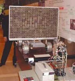
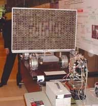
A solar battery was mounted to the rover to receive the laser light (see figure). The cell powered the communications receiver, motor, steering controller, light-detecting circuitry, and mechanical parts of the solar battery panel so that the maximum amount of light could be collected.
Although energy was successfully transferred more than 100 m, obstacles remain before the rover can be controlled fully. To produce maximum power, the battery panels mounted on the rover must be designed so that each element performs optimally even if the distribution of the laser light is not uniform. The configuration of the battery panels must be optimized and the energy conversion efficiency improved. After the scale-model rover is tested and shown to be fully controllable, the entire system including the satellite and mother ship will be developed.
Courtesy O plus E magazine, Tokyo
null
REFLECTIVE INKS
Metallic printing makes ephemeral images
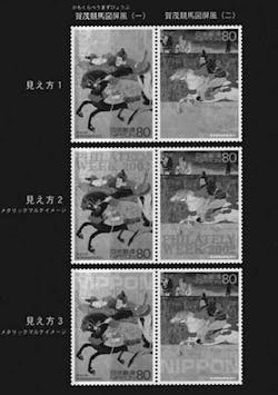
TOKYO-The Ministry of Public Management, Home Affairs, Posts and Telecommunications has developed a commemorative postage stamp that shows different words depending on the observation angle. The stamps have traditional Japanese artwork taken from a famous screen depicting scenes from the annual Kamowake Horse Races that take place at the Kamowake-Ikazuchi Shrine in Kyoto. The two scenes on the stamps are considered to be the most crucial and dynamic of the six scenes depicted on the screen.
The characters that change depending on observation angle are created with a technology called metallic multi-image (MMI) developed by the Printing Bureau of the Ministry of Finance. The MMI method uses metal-powder-based inks and standard printing methods used for conventional color inks. The printing mechanism is controlled so that different colors appear on the surface depending on observation angle, thus showing different characters.
Light generally reflects off a printed surface with two components: colored light that is diffused after reflecting off the ink particles, and white light that is reflected perpendicularly to the light source (commonly known as "shine"). By combining these two effects, the characters can be made to blend into the background at the angles when the shine component is strong, and appear at high contrast to the background at other angles. Conversely, the characters can be made to appear at angles when the diffused light component is strong, and blend into the background at other angles.
These stamps were printed using both these configurations by sectioning the stamps into thin strips and alternating these two types of printing. Thus, depending on the angle, two different sets of characters emerge. These stamps are now sold nationwide at post offices in Japan.
Courtesy O plus E magazine, Tokyo
null


