Novel VCSEL designs deliver high single-mode output power
By Jean-Francois P. Seurin, Shun Lien Chuang, Leo M. F. Chirovsky, and Kent D. Choquette
Improvements in VCSEL technology have generated innovative designs for applications requiring high single-mode powers, including the selectively oxidized VCSEL and the I2-VCSEL.
Used in a wide variety of applications, compact, efficient, and manufacturable lasers operating in the milliwatt-level output-power range are increasingly in demand. Applications include high-speed laser printing (780 nm), optical storage (blue/green wavelengths), laser line-of-sight optical communications (850 nm), and long-wavelength telecommunications (1.3, 1.55 μm). These applications require a Gaussian-type circular intensity profile that allows beam propagation over large distances, as well as focusing of high power into small spots or single-mode fibers. Vertical-cavity surface-emitting lasers (VCSELs) have attracted much attention in recent years because of their potential for high-volume low-cost manufacturability, simple two-dimensional (2-D) array fabrication, and superior beam quality.
A typical VCSEL structure consists of a short cavity (1 or 1.5 wavelengths thick) sandwiched between two stacks of alternating quarter-wavelength high and low refractive-index layers known as distributed Bragg reflectors (DBR). The active layer lies in the center of the cavity and is usually a few hundred Angstroms thick. The light oscillates perpendicular to the plane of growth and the high reflectivities of the DBRs (typically >99.9%) compensate for the small gain medium thickness.
Advantages of VCSELs include single longitudinal-mode operation and a circular emission pattern that allows for better coupling into optical fiber without the need for beam-shaping optics. The planar structure also allows much easier fabrication and testing processes, resulting in higher device yield, and makes possible the fabrication of 2-D laser arrays.
Selective oxidation
An innovative process, selective oxidation of semiconductor material, has produced the most efficient and smallest VCSEL devices to date, as well as those with the lowest threshold current.1 In these devices a semiconductor layer is oxidized to form a thin intracavity aperture.2 Because the oxide is insulating, the aperture will confine the injected carriers. Also, because the oxide has a lower index of refraction than the semiconductor material, this aperture can serve as a beam guide for the optical intensity. The increase in performance of oxide VCSELs is mainly due to the stronger mode confinement and better overlap with the gain medium.
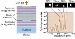
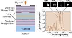
Devices with small oxide apertures (2 x 2 to 4 x 4 μm2) can operate in a single mode. Devices with 3.5-μm diameters have achieved single-mode output powers of 4.8 mW.3 Devices with larger apertures, however, will rapidly operate in multiple transverse modes. The spatially and spectrally resolved output of a double-oxide VCSEL with 5 x 5 μm2 apertures exhibits strong multitransverse-mode behavior (see Fig. 1). The design constraints and fabrication tolerance (about 1-μm accuracy) on the oxide aperture for single-mode VCSELs are quite narrow, and the maximum allowable size for the oxide window for single-mode operation limits the potential for high-power applications.
Cold-cavity designs
To obtain high-power output, the area of the device needs to be increased, which increases the number of transverse modes. Furthermore, the wavelength separation and differences in optical losses between these transverse modes decrease. In the limit of very large emission apertures, there are many transverse modes with wavelengths and losses equal to the plane-wave limits. Combining high-power and single-mode operation is therefore very difficult. The methods used to obtain single-mode operation are based on "cold-cavity" considerations. The basic idea is to increase the optical losses of higher-order modes.
A popular design uses the antiguiding-structure concept. In this approach, the effective waveguide generated in the VCSEL structure has a higher cladding refractive index than the core region, thus generating antiguiding.4 High-order transverse modes will suffer increased radiation losses to the point that they will not lase below a certain injection current. The main disadvantage is the fundamental mode also incurs large radiation losses inherent to antiguiding structures, increasing threshold and limiting maximum output power.
The I2-VCSEL approach
Another approach relies on modifying the overlap of the optical mode with the gain profile (also referred to as mode-selective gain) to generate high-power single-mode operation.5 A device known as the implant apertured index-guided VCSEL (I2-VCSEL) relies on two separate processes to independently control the beam diameter and the lateral extent of the active region (see Fig. 2).6
The main advantage of the I2-VCSEL is the independent control of the diameter of the etched gallium arsenide (GaAs) pillbox, which defines the index-guiding aperture, and the diameter of the ion implant, which defines the current aperture, by using different sets of masks. Photolithographic processing enables concise control of the diameters. Contrary to an oxide aperture, the implant aperture is invisible to the optical beam. The current aperture can therefore be made smaller than the index-guide aperture to reduce the overlap of the higher-order modes with the gain profile while at the same time keeping a sufficient fundamental mode/gain overlap. A smaller current aperture not only could inhibit lasing of higher-order modes, but also could minimize the threshold current of the fundamental mode.7
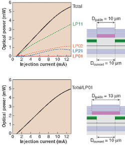
To extend this work to high-power devices, we simply increase the diameter of the current aperture to 10 μm and analyze the influence of the index-guide aperture size on the multimode behavior of these devices (see Fig. 3). For equal aperture sizes, not only does the device operate in multimode, but the fundamental mode power remains negligible throughout the entire range of operation. Experimental measurements confirm this behavior.
As the index-guide diameter is increased, the mode diameters will also increase and the overlap with the gain profile will decrease. Because higher-order modes have a relatively larger amount of their power spreading off center than does the fundamental mode, they suffer more from this loss of overlap. Eventually, the modal threshold gains of higher-order modes will become too high and the fundamental mode will be the only one to lase (for a beam-guide diameter of 13 μm).
Although the slope efficiency does not seem affected, there is a small decrease in maximum achievable power. The increase of the index-guide diameter also increases the fundamental mode threshold current, although not by a significant amount.
The single-mode performance of this device depends primarily on the spatial profiles of the transverse modes and their overlap with the gain profile, and not so much on the cold-cavity resonant wavelengths and losses. For the 13-μm index-guide-diameter device, the modal resonant wavelengths and losses are actually very close. In fact, in the limit of very large index-guide diameters, all the transverse modes will have the same resonant wavelengths and optical losses (equal to the plane-wave values). Even though the effective waveguide defined by this very large index-guide will support a large number of transverse modes, only the fundamental mode will lase if the current aperture size is set appropriately.
ACKNOWLEDGMENTS
The work was done at the University of Illinois at Urbana-Champaign using Illinois-VCSEL software (contact [email protected]). The I2-VCSELs were fabricated at Lucent Technologies Bell Laboratories (Holmdel, NJ). The double-oxide-aperture VCSELs were fabricated at Sandia National Laboratories (Albuquerque, NM).
REFERENCES
1. K. D. Choquette et al., Appl. Phys. Lett. 70, 823 (1997).
2. J. M. Dallesasse et al., Appl. Phys. Lett. 57, 2844 (1990).
3. C. Jung et al., Electron. Lett. 33, 1790 (1997).
4. Y. A. Wu et al., IEEE J. Select. Topics Quant. Electron. 1, 629 (1995).
5. K. D. Choquette et al., Proc. SPIE 3946, 230 (2000).
6. L. M. F. Chirovsky et al., IEEE Photon. Technol. Lett. 11, 500 (1999).
7. J.-F. P. Seurin et al., Appl. Phys. Lett. 77, 3686 (2000).
JEAN-FRANCOIS P. SEURIN is senior device engineer with Princeton Optronics, 1 Electronics Dr., Mercerville, NJ 08619; e-mail [email protected]. SHUN LIEN CHUANG and KENT D. CHOQUETTE are professors in the Department of Electrical and Computer Engineering, University of Illinois at Urbana-Champaign, Urbana, IL. LEO M. F. CHIROVSKY is manager of device development with Cielo Communications, Broomfield, CO.


