Sealed CO2 lasers find new applications
By John Law And Cathy Mcbeth-Schomber
Radio-frequency-excited sealed carbon dioxide lasers are increasingly being used to mark, cut, drill, and weld inorganic materials.
It is well-known that low-power radio-frequency (RF)-excited sealed carbon dioxide lasers can cut plastics, engrave rubber, mark wood, and process many other organic materials. Less well-known is the fact that these lasers can mark and weld metals, mark glass, and drill vias in copper-clad printed-circuit boards, replacing other, higher-cost lasers or different technologies. Their expanded usage is largely a result of improved process developments, as well as new laser designs.
The low cost and minimal maintenance requirements of low-power carbon dioxide (CO2) lasers make them appealing to many manufacturers. Sealed CO2 lasers are small and rugged, with operating lifetimes in excess of 35,000 hours. They can be mounted on robotic arms or moving-gantry systems and are simple to integrate. As laser manufacturers introduce new CO2 laser designs that are smaller, air-cooled at higher powers, and offer faster rise times and near-perfect beam quality, the number of tasks these lasers can perform continues to increase.
Marking metals
Metals processing is almost always associated with Nd:YAG lasers. Low-power CO2 lasers, however, can mark a number of metals, including mild and stainless steels, inconels, and titanium. A 60-W air-cooled laser recently introduced by Synrad, for example, has a fast rise time and high beam quality that make it especially well-suited to metal marking. The laser can be aligned to a galvanometer-based marking head to create a compact package that offers users a small footprint and costs considerably less than a YAG system. With so many industries requiring text, graphics, bar, or other codes to be marked on various metal parts, the potential for this application is great.
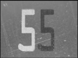
Metal-marking applications generally use CO2 lasers emitting from 50 to 200 W. Marking is accomplished in one of two wayswith or without surface melting (see Fig. 1). In the latter case, discoloration results from surface oxidation when the material is heated by the focused laser beam. In the former, additional energy is applied to melt the surface of the material, and the molten metal resolidifies to form the mark. The type of mark that is produced is controlled by energy input, the atmosphere the mark is made in, and the material being marked.
Because metal marking is a high-energy process, smaller spot sizesand therefore shorter focal-length lensesproduce the highest-quality marks and fastest cycle times. This comes at the expense of the overall marking field size. For steels, the largest practical spot size is 300 μm, while the smallest is about 100 μm. The resulting field sizes for these spot sizes are around 4 and 1.2 in., respectively. The power density of a 100-μm spot size is nine times that of the 300-μm spot; clearly, minimizing the focal length and field size requirements significantly improves cycle times. For a given optical system, a laser with higher beam quality will provide a smaller spot and therefore increased processing power. Spot size also relates to the size of the marks themselves. With most material, the smallest character height possible is around five times the spot size. A 100-μm spot size is capable of producing character heights down to 0.02 in.
The surface finish of the metal also affects the outcome. A rough finish, such as bead-blasted metal, is less reflective than a smooth finish and therefore requires less energy input to mark. Bare aluminum, copper, and brass cannot be marked directly by low-power CO2 lasers; however, anodized and painted surfaces provide clear marks often using very low powers (on the order of 10 W).
Welding metal
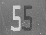
Welding is usually associated with high-power flowing gas CO2 or pulsed Nd:YAG lasers. Sealed CO2 lasers, however, can be used to weld some thin metals and foils. The same metals that are suitable for markingsteels, inconels, and titaniumcan be welded by sealed CO2 lasers with output powers of 100 W and up (see Fig. 2). Such lasers can be used for spot welding near heat-sensitive materials like glass or electronic components, as well as for seam welding. Welding of two different metals is also possible as long as the metallurgical combinations are compatible.
Generally, the laser will need to be pulsed when welding at power levels around 100 W, while continuous-wave output requires higher power levels. This is a consequence of the reflective nature of metals at the 10.6-μm CO2 wavelength. The reflectivity of metals is temperature-dependent. As the metal temperature rises, reflectivity decreases and laser coupling increases. The high peak power of a pulsed laser or high average power is needed to raise the material temperature and facilitate absorption. As in metal marking, a small spot with high power density is important.
Marking glass
New techniques have made it possible to produce crisp, high-quality marks directly on glass with sealed CO2 lasers, making them an attractive alternative to traditional glass-marking methods and expensive solid-state lasers (a 25-W CO2 laser provides sufficient power for most glass-marking applications). By definition, CO2 lasers mark glass by fracturing its surface, so in all cases, a certain amount of fracturing of the material is necessary. Excessive fracturing, however, can result in difficulties with readability, potential weakening of the material, and most notably, the formation of loose chips. These problems can be eliminated by carefully controlling the amount of fracture that takes place during the marking process.
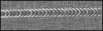
Three techniques are used to control the amount and type of fracturing induced on the glass surface. The first relies on using multiple laser passes, the second uses discrete spots to form ring fractures, and the third produces crazed surface fractures (see Fig. 3).

A mark made using a single pass will produce a bold visible mark on glass, but fractures and stress patterns will extend perpendicular to the direction of laser motion. After a period of timeeven days after the mark is madethese perpendicular fractures will form new fractures adjacent to the marked area, which can form debris and affect readability. Using multiple laser passes allows the material adjacent to the desired mark area to be heated through conduction, which helps to form a stress gradient that reduces the chances of secondary fracturing. This method is effective for marking on soda-lime and borosilicate glasses. Single pass marks work well on fused silica and quartz glasses due to their low expansion coefficient.
In the second method, a series of ring fractures can be used to form text, bar codes, square or rectangular codes, and other codes. The glass goes through a heating and cooling cycle that produces a low-density circular formation. The glass expands when heated, pushing against the surrounding material. When the softening point is reached, the glass expands radially, forming a dome of low-density material that protrudes above the surface. After heating, the glass contracts back to its original surface position, but the relaxation time is such that the entire low-density formation cannot return to its starting point before the softening temperature is reached.
The Gaussian nature of the spot results in greater heating at the spot center. This hot region returns close to its original position and forms an anchor for the ring fracture. The juncture between low-density formation and normalized material allows for the formation of stable circular fractures. This method works well for marking common optical materials and tempered, chemically strengthened, or plain soda-lime float glass.
The third method involves the same heating and cooling cycle that gives rise to the changes in specific volume of the glass surface. However, a larger spot size is used (typically around 500 μm) and does not produce the same sharp junction used in the ring-fracture method. The mark produced is not immediately visible and requires a slight amount of pressure to begin fracturing that will cascade along the laser marked area. Filled text, graphics, and codes can be produced with no debris. As this method requires a pristine surface, the high quality of automotive glass produces exceptional results.
Drilling applications
Drilling viasthe hundreds of holes for mounting electronicson printed circuit boards is another area in which the role of CO2 lasers is expanding. Previously, sealed CO2 lasers were used to drill only through the dielectric material, while Nd:YAG lasers drilled through the copper conformal mask. Although copper reflects the CO2 wavelength, new process developments have made it possible to drill through copper with CO2 lasers. By oxidizing the copper surface of the circuit board, absorption of the CO2 laser energy is increased, thereby eliminating the need for a two-laser system.
Low-power CO2 lasers are being increasingly used for drilling high-aspect-ratio holes in ceramics. Hole diameters smaller than the laser spot size can be drilled using appropriate pulsing conditions. A short pulse length with a low repetition rate enables the ceramic to conduct heat away from the drill zone. The holes are formed via tip processing, a technique in which only the central part of the Gaussian beam is used, reducing the effective beam size.
REFERENCES
1. G. Allcock et al., J. Appl. Phys. 78(12), 7295 (1995).
2. A. C. Tam et al., IEEE Trans Mag. 33(5), 3181 (1997).
3. D. Kuo et al., IEEE Trans. Mag. 33(1), 944 (1997).
JOHN LAW is an applications engineer and CATHY McBETH-SCHOMBER is marketing manager and at Synrad Inc., 4600 Campus Place, Mukilteo, WA 98275; e-mail: [email protected].