Deep-ultraviolet light sources for photolithography fall into two categories: those intended for exposure illumination and other high-power applications, and those used in measurement tools. For exposing photoresist, excimer lasers—with their high average power—are the light source of choice. Measurement tools, however, require only small amounts of optical power, so they can get by with smaller, simpler solid-state lasers that do not require handling of toxic gases.
Often, such measurement tools require wavelengths that match the excimer-laser wavelengths used for exposure—wavelengths that cannot be directly reached by quadrupling the frequency of a relatively inexpensive Nd:YAG laser. Therefore, designers of light sources for these tools must take other routes. Engineers at Actinix (Soquel, CA) have now developed and patented two approaches to matching the 157-nm fluorine and 193-nm argon-fluoride excimer wavelengths.
Matching argon fluoride
The conventional way to produce 193 nm from a solid-state laser is to frequency-quadruple a tunable Ti:sapphire or alexandrite laser—a complicated three-stage process, according to Jim Jacob, president of Actinix. "It involves polarization rotation with waveplates and the recombination of beams with multiple beamsplitters—in short, a lot of optical components to go from 772 to 193 nm," he says. In contrast, the Actinix approach combines the 710-nm output from an optical parametric oscillator (OPO) with the Nd:YAG fourth harmonic, both derived from the same 532-nm pump beam.
Though the process may sound complicated, it is much simpler than Ti:sapphire and alexandrite-based schemes; as a result the Nd:YAG and OPO-based system contains fewer optical surfaces. A second advantage for measurement is that the coherence length of the Actinix system is short (2 mm), eliminating stray interference fringes in optical systems such as microscopes.
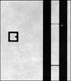
The light source produces 0.5-mJ pulses at up to a 15-Hz repetition rate from a package 45.7 x 33 x 12.7 cm in size. It is incorporated into a high-resolution photomask transmission and phase-measurement tool made by Actinix that is able to resolve features less than 200 nm in size. The laser beam is split into two components. The first, used for imaging, is sent though a fiber bundle and rotating diffuser for beam homogenization; the associated 0.75-numerical-aperture objective lens is made by Corning Tropel (Fairport, NY) and has a 100-μm field of view and an 8-mm working distance. A charge-coupled-device (CCD) camera with a 193-nm-sensitive coating captures the image. The second part of the beam is passed through a pinhole and scanned across the photomask under test to spatially probe its features; a photomultiplier tube as well as the CCD catches the resulting output (see Fig. 1).
Matching fluorine
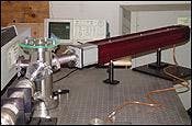
Still in the preliminary stage, the 157-nm light source developed at Actinix is based on Raman generation in hydrogen (H2) gas, in which pulsed laser light excites vibrational transitions in H2 molecules. The output spectrum contains the pump beam and several sidebands at frequencies both above and below the pump frequency. When H2 is pumped with frequency-quintupled light (213-nm wavelength, 6-ns pulse duration, 25-mJ energy) from an Nd:YAG laser, the resulting fourth anti-Stokes line at 157.256 nm happens to closely match the emission wavelength of fluorine excimer lasers.The setup contains a Raman cell filled with H2 to a pressure of 1 to 20 bar (see Fig. 2). A calcium fluoride dispersion prism separates the spectral lines. With a single pump laser, conversion efficiency to the fourth anti-Stokes line is about 0.1%. The coherence length of the free-running Raman system is 30 cm. An improved version of the apparatus will contain a second Raman cell optimized to generate the first Stokes line, seeding the second Raman cell and increasing both conversion efficiency and stability.
"Near-at-wavelength applications will benefit from this source that has a narrow natural linewidth," says Jacob. (High chromatic dispersion in optical materials at 157 nm, coupled with the lack of glass variety needed to correct chromatic dispersion in lenses, means that narrow-linewidth sources are especially necessary at this wavelength.) Additionally, the source offers multiple lines in the vacuum ultraviolet, so it can be used as a spectral "picket fence," Jacob notes. The primary disadvantage of the source is that it requires high pump energy and is thus limited to low-repetition-rate operation, although the rate could be upped to the kilohertz regime in the future as diode-pumped solid-state lasers scale up, says Jacob. This source as well will find application in photomask measurement tools.
About the Author
John Wallace
Senior Technical Editor (1998-2022)
John Wallace was with Laser Focus World for nearly 25 years, retiring in late June 2022. He obtained a bachelor's degree in mechanical engineering and physics at Rutgers University and a master's in optical engineering at the University of Rochester. Before becoming an editor, John worked as an engineer at RCA, Exxon, Eastman Kodak, and GCA Corporation.

