WHITE-LIGHT LEDS: Pitted LEDs emit broad spectra
Two types of phosphor-free white-emitting LEDs have been developed that appear, at first glance, to rely on the same concept for white-light emission; however, when examined in detail, they are different.
The relaxed version
Scientists at Peking University (Beijing, China) are crafting phosphor-free gallium nitride (GaN)-based white LEDs that rely on a “strain adjusting” indium gallium arsenide (InGaN) interlayer to produce blue and yellow luminescence. While this isn’t the first time such an LED has been made, the researchers have carefully studied the origin of the luminescence, determining that it arises from indium-rich areas (yellow emission) and indium-depleted edges (blue emission) in inverted pyramidal pits on the LED’s surface.1 The pits are formed when the strain-relaxation process induces dislocations in the InGaN interlayer.
The LED, which was grown on sapphire, has a InGaN layer (with an indium molar fraction of 0.15) squeezed between its GaN buffer layer and its light-emitting multiple quantum wells (MQWs). Because the periods of the InGaN and GaN crystal lattices are different, the InGaN layer strains as it is deposited, trying to fit the GaN layer. As the InGaN layer thickens, it reaches a critical thickness and then loses its strain, relaxing by forming dislocations. Further deposition results in the formation of six-sided pyramidal pits at the ends of the dislocations; the pits vary in size and spacing.
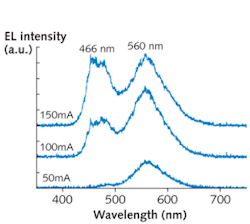
The properties of the white LED were studied by measuring room-temperature electroluminescence (EL) and cathodoluminescence spectra, while high-resolution x-ray diffraction and scanning-electron microscopy were used to help understand the relationship between the device’s structure and its optical properties.
When the injection current is low, the LED emits mainly yellow (560 nm) light. As the injection current increases, the blue (466 nm) portion of the emission increases, and the yellow portion eventually saturates, say the researchers. For example, at a current of 50 mA, the LED is yellow, but when the current is raised to 150 mA, the EL spectrum corresponds to a while-light source with a color temperature of 4972 K and CIE chromaticity-diagram coordinates of 0.30, 0.37 (see Fig. 1).
Analysis showed that the MQWs grown over the pyramidal pits had fluctuating indium content, with indium-rich regions at the bottoms of the pits and a scarcity of indium at the pit edges, causing the two different emission wavelengths. The yellow-emitting depths saturate as the current grows stronger, while the blue-emitting edges increase in emission.
The orderly version
Using photolithography, researchers at the Gwangju Institute of Technology (Gwangju, Korea) and NiNEX (Pyongtaek, Korea) have created a GaN-based LED with an array microstructure on its surface; the unit cell consists of a four-sided trapezoidal pit with a flat bottom (see Fig. 2).2 The pits take such a shape because the sloped side facets are semipolar GaN crystalline planes, while the level surface around the pits is a different crystalline plane, the c-plane. The flat pit bottoms are of silicon dioxide (SiO2). The device’s MQWs are grown on the sides of the pits and on the level surface above.
When an injection current is applied, the sides of the pits emit blue light, while the surrounding upper surface glows in a color ranging from red to yellow (depending on the current). This is the reverse of the Chinese LEDs, which glow yellow down in the pits and blue farther up; however, like the Chinese LEDs, the Korean version changes from a warm color (in this case, red) to a cool blue as the current is increased. The Koreans attribute the color properties of their device to three things: a higher indium concentration on the c-plane, which creates the two colors; the lower resistance of the c-plane, which gets the red aglow at low currents; and the saturation of the c-plane at high currents, which then lets the blue predominate.
The distinction
Both LEDs are GaN-based, phosphor-free, and have pockmarks all across their emitting areas. So what’s the difference? The pits in the Chinese version are variable in size and a natural result of strain relaxation; in addition, the fabrication method needs no photolithographic step, and is thus perhaps simpler. In contrast, the indentations in the Korean LED are regular and controlled in width and shape, and might allow additional control of the LED’s properties in manufacture.
In either case, if a non-phosphor-containing white LED could be made to be as efficient as an ordinary white LED, it could very well become the new standard for LED illumination. The reason? It would likely last longer, as there is no phosphor to degrade.
REFERENCES
- H. Fang et al., Applied Phys. Lett. 93, p. 261117 (published online Dec. 31, 2008).
- C.-Y. Cho et al., Applied Phys. Lett. 93, p. 241109 (2008).
About the Author

John Wallace
Senior Technical Editor (1998-2022)
John Wallace was with Laser Focus World for nearly 25 years, retiring in late June 2022. He obtained a bachelor's degree in mechanical engineering and physics at Rutgers University and a master's in optical engineering at the University of Rochester. Before becoming an editor, John worked as an engineer at RCA, Exxon, Eastman Kodak, and GCA Corporation.