Real-world systems demand application-specific designs
DAVID SCHIE
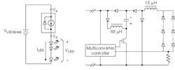
Harnessing the long-lifetime and high-efficiency benefits of high-brightness LEDs (HBLEDs) in real-world applications relies as much upon systems and components as it does on the materials science of the HBLED itself. Unlike the laboratory, however, real-world challenges include high temperatures, small form factors, regulatory requirements for EMI (electromagnetic interference), power quality and efficiency, varying input voltages, wide conversion ranges, dimming requirements, manufacturing variations, and dramatic loss of effective HBLED lifetime in the face of nonideal drive waveforms. So driving high-brightness LEDs, of course, requires an in-depth understanding of the specific application. It also involves numerous tradeoffs and selecting from a wide variety of possible solutions that include recently introduced power-electronics techniques and emerging technologies requiring additional research (see Fig. 1).
High-brightness LEDs are low-dynamic impedance loads, in which a very small voltage change causes a large change in current. The high-gain element makes many solutions difficult to stabilize over the LED operating range and manufacturing tolerances cause differences in forward voltages for a given current—not to mention spectrum and lumen output parameters. With such concerns in mind, drivers for high-brightness LEDs can be divided into two categories: those that attempt to regulate an output voltage over differing input conditions and requirements and then use a regulator (such as a current source or resistor) to regulate current ("voltage mode"), and those that directly regulate current and allow high-brightness LEDs to "create" an optimal voltage in response—such as a "current-mode" multiconverter.
In voltage-mode solutions, the variation in LED forward voltages means that the output voltage must be larger than the highest possible forward voltage across any string of LEDs plus the worst-case dropout across the regulator element (see Fig. 2). Strings of LEDs can easily be paralleled and for parallel strings the voltage across the regulator element plus differences in forward voltage multiplied by the full operating current is wasted energy. In current-mode solutions, energy efficiency is maximized but the need to measure a single current (either a sampled string or the total combined current) makes matching difficult.Lifetime
The lifetime of LEDs is a contentious issue because of the various types of high-brightness devices on the market, their varied lifetime ratings, and their differing sensitivities to environmental conditions such as temperature or drive waveform. There is also a lack of research in the area upon which to base fundamental design decisions.
Empirically, high-brightness LED manufacturers have concluded that lifetime will dramatically decrease if the LEDs are "overdriven." Studies have also shown lifetime degradation related to drive waveform variation. As lifetime is related to loss of lumen output, rather than catastrophic failure, perceived poor performance can begin long before system failure.
Justifying LED driver solutions that maximize the lifetime of high-brightness LEDs is difficult. Because of the high cost of the devices and filtering needed for long lifetimes, many designers ignore the exponential loss of HBLED lifetime because the sale is, in the absence of studies and lifetime evidence, based on the initial rather than long-term performance. Most commonly, LED lifetime is traded for size, cost, and driver lifetime enhancement by reducing filtering and increasing the crest factor.
Filtering and crest factor
Filtering is required to meet requirements such as power factor (PF), total harmonic distortion (THD), and electromagnetic interference/compatibility (EMI/EMC) requirements in applications powered by AC as well as DC sources. Filtering the output drive waveforms brings the high-brightness LED electrical stimulus in line with the waveforms used to rate LED lifetimes in laboratory conditions, but cost and form factor suffer as a result. Lack of adequate filtering can produce equivalent average currents with a dramatic loss of lifetime.
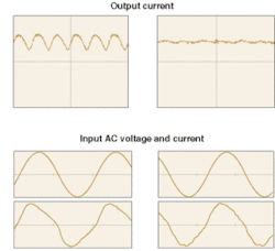
An important measure of overdrive related to filtering is the crest factor, which measures the ratio of peak-to-rms (root mean square) current (see Fig. 3). In the case of an offline driver, to reach the full rated average operating current without significant and expensive filtering, the driver must overdrive the device for a period of time to compensate for the time it is underdriving the HBLED. Overdrive times can be long due to the low frequency 100- to 120-Hz ripple that can be expected, causing heating that can subsequently cause an exponential decay in LED lifetime (yellowing of epoxy dome and materials damage, for instance). The alternative is to drive the HBLED so that the peak current does not exceed the rated current. This is not economical, however, because more HBLEDs are needed to compensate for lumen loss.Filtering presents an obstacle because of the lack of filters that can work at high temperatures, store large quantities of energy, and fit into small form factors. In reality, electrolytic capacitors are the only option for small-form-factor bulk filters in many AC applications. Unfortunately, electrolytic capacitors are perhaps the least reliable components in any power supply. In fact, the best commercially available electrolytic capacitors have a rated lifetime of only 5000 hours at 105°C. As a rule of thumb, life doubles for each 10°C below the 105°C temperature at which the capacitors are rated, which then brings them into the lifetime range of HBLEDs at 60°C or below (ignoring derating alternatives that unreasonably increase cost and size). Many high-brightness applications operate at temperatures far higher than 60°C, however, meaning that electrolytic-based systems will not produce the long lifetimes promised of the high-brightness devices.
Understanding application and requirements
Drivers for LEDs range from simple resistors to complex power-electronics assemblies. Clearly certain solutions are more suited to different applications—some specifically intended for AC applications or for DC—but in many cases the advantages, or disadvantages, of a given solution are not immediately clear. Typical solutions in other applications may not be ideal for HBLEDs because the high-brightness environment is often not typical (click here to see table).
An offline light-bulb replacement driver might require the following to be met simultaneously: regulatory agency requirements (PF greater than 0.9, THD less than 20%), a form factor that fits into the Edison base of a standard lamp, continuous operating temperature above 90°C (in a downlight for example) for more than 20,000 hours, compatibility with phase-control dimmers, overvoltage and brownout protection, 85- to 135-VAC operation while maintaining a constant 700-mA output (nonisolated) with a crest factor of less than 1.3, soft start, and EN61000 radiated and conducted EMI requirements.
A first-glance solution for this could be a flyback or buck-boost converter. Such a solution, however, would not be ideal. Ignoring reliability problems, if a large high-voltage electrolytic capacitor were used at the input, a high power factor would not be possible. The alternative filter location—the output—suffers because the low dynamic impedance of the output LED string means that output voltage variation must be minimized. This means significant low-frequency filtering at low voltages and low delta-V energy storage to maintain the load current during the time that the rectified AC input voltage is low.
A multiconverter is an alternative that minimizes filtering due to a high-voltage central-filter energy-storage element, and a converter between this central filter and the output. The fact that the node is high voltage means a smaller relative voltage variation (compared to storage at lower voltages) occurs when supplying output power during the AC dropouts (that is, smaller capacitor form factors for energy storage or higher reliability components such as films can be used). At the same time, the switching power supply between this capacitor and the output allows the switch-mode power-supply (SMPS) controller to reject the ripple and thereby compensate for the low dynamic impedance of the LEDs. At first glance, the need for two inductors seems cumbersome, but the pair can actually be cost-competitive with a single flyback transformer.
Multiconverters may offer a good solution for low-power, nonisolated, offline applications. For applications requiring isolation, or in the case of high output power, other single-switch power-factor-correction (PFC) topologies such as boost integrated with flyback rectifier/energy-storage DC (BIFRED) or boost integrated with buck-boost rectifier/energy-storage DC (BIBRED) can be used. Additionally, the Cuk converter and the single-ended primary-inductance converter (SEPIC) hold the promise of low-cost bucking or boosting solutions that reduce noise in automotive and other DC applications.
Click here to download LED drivers: advantages and disadvantages pdf.
David Schie wrote this article while he was vice president of Supertex, 1235 Bordeaux Drive, Sunnyvale, CA 94089. He is currently the director of integrated circuit design at Maxim Integrated Products, 120 San Gabriel Dr., Sunnyvale, CA, 94086; e-mail: [email protected].


