LED OPTICS: Efficient LED collimators have simple design
Two nonimaging LED collimating lenses developed by engineers at the Chinese Academy of Sciences and Xi’an Jiaotong University (both in Xi’an, China) were designed using a simple and quick process, unlike the complex iterative software design usually used for LED optics.1 The collimators are very efficient and focus at least 80% of an LED’s light within a 5 m radius that is 200 m away from the light source.
Refractor on the outside
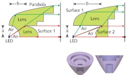
The first type of lens consists of four types of surfaces. The first surface has an aspheric profile and is designed to collimate light emitted from the LED at smaller cone angles. The second surface is a parabola with the LED at the focus (see figure); this surface collects and collimates light from the LED at large cone angles. The third surface is a spherical section near the LED designed to pass rays into the lens at normal incidence to the surface. The fourth is a so-called ladder surface, through which rays reflected from the parabolic surface exit without a change in direction; the ladder-like shape is to minimize the volume and weight of the lens.
The design of the surfaces is straightforward, with only a couple of things to keep in mind. First, surface 1 must end at or before the diameter at which a ray from the LED strikes the surface at the critical angle (beyond which the ray would be totally internally reflected). Second, the ladder shape must not get in the way of the ray from the LED that reflects from the outer edge of the parabola.
In a simulation, a 1 × 1 mm LED chip emits at a wavelength of 500 nm. One hundred thousand rays are traced to an illuminated plane 200 m away. The lens is made of molded polymethyl methacrylate (PMMA) and is assumed to be nonabsorptive and free of scatter. Here, the radius of the spherical section is “a” and the axial distance from the LED to the edge of the center asphere is “b.”
For a lens of type 1, models were created with a = 8 mm and b = 8 mm; a = 14 mm and b = 14 mm; a = 8 mm and b = 20 mm; a = 14 mm and b = 20 mm; and a = 20 mm and b = 20 mm. As expected, the larger lenses produced smaller collimated spots, with the lens with b = 20 mm and a = 20 mm producing a beam with 94.9% of rays falling within a 3.5 m light-spot radius at 200 m, and the lens with a = 8 mm and b = 20 mm producing a beam with 98.5% of rays falling within a 4 m light-spot radius at 200 m.
Refractor on the inside
The second type of collimating lens also has four surface types. The first surface is a ladder-type flat surface; the second is an axial aspheric refractor; the third is an aspheric reflector; and the fourth is a cylindrical surface passing rays to the reflector.
In this case, modeling showed that a lens with the cylinder radius a = 8 mm and the axial distance to the aspheric refractor edge b = 20 mm showed a spot at 200 m, with about 90% of the light rays falling within a 5 m radius ( similar results held for most other modeled lens dimensions as well).
The two lens types showed efficiencies (the percentage of light from the source successfully passing through the lens) of about 90% and 99%, respectively. While the second lens type has a lower efficiency, it is also much shallower than the first type for the same a and b: For a = 8 mm and b = 20 mm, the first type has a depth of 103 mm, while the second is only 38 mm deep.
The researchers note that many LEDs today have chip sizes smaller than 1 × 1 mm; using these LEDs will produce even better results.
REFERENCE
1. G. Wang et al., Appl. Opt., 51, 11, 1654 (April 10, 2012).
About the Author

John Wallace
Senior Technical Editor (1998-2022)
John Wallace was with Laser Focus World for nearly 25 years, retiring in late June 2022. He obtained a bachelor's degree in mechanical engineering and physics at Rutgers University and a master's in optical engineering at the University of Rochester. Before becoming an editor, John worked as an engineer at RCA, Exxon, Eastman Kodak, and GCA Corporation.