Gas systems improve materials processing

As lasers have become more popular in the industrial marketplace for a variety of machining processes, the demands placed on gas-delivery systems have increased. Most high-powered industrial lasers are carbon dioxide (CO2), which require gas both as the lasing medium and for control of the process. Nd:YAG lasers, which are popular for some applications, are solid-state and do not need gas for beam generation, but they do require gas at the workpiece to assist them in cutting. Gas-delivery systems ensure that these lasers get their gases at the right purity levels and the correct pressures.
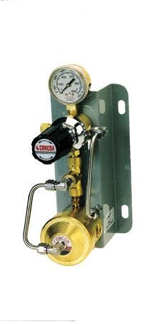
FIGURE 1. Regulator with stainless-steel diaphrams connects the gas supply to laser equipment used in industrial machining processes. The high-flow capacity, high delivery-pressure dome-loaded system works with either a liquid supply or high-pressure gas supply and can deliver up to 500 pounds per square inch and 6000 cubic feet per hour of nitrogen.
Carbon dioxide lasers require that a gas mixture be supplied to the resonator for laser beam generation-these gases must conform to a certain purity level. Minimum requirements for the delivery system are dual-stage regulators equipped with metal-preferably stainless steel-diaphragms and other wetted surfaces compatible with the gases being used (see Fig. 1). Gas-delivery systems for beam-generating gases must include regulation equipment meeting these basic requirements, but the system can also be designed to supply multiple lasers, thereby reducing the need for changing multiple gas cylinders. Different styles of CO2 lasers-slow-flow, transverse-flow, fast-axial, and transversely excited atmospheric pressure (TEA) systems-may have differing requirements for the gases and equipment.
The integrity of the gas supply system for CO2 lasers must be maintained at all times because outside air is the main source of impurities such as moisture, oxygen, and hydrocarbons. Oxygen, even in trace amounts, can form ozone by combining with dissociated molecules from the CO2, leading to erosion of the optical coatings. When hydrocarbons are present in the laser resonator, small carbon flakes will be burnt onto the surface of the optics, leading to power losses and shorter lifetime of the optics. Moisture will support reactions with the oxygen and hydrocarbon and can also react with the decomposed laser gas. The formation of negative ions such as H-, OH-, and H3O+ will produce instabilities in the electrical discharge. Gases with purity levels of grade 4 (99.99 %) can have impurities of 100 parts per million (ppm). Users should always specify the maximum levels of oxygen, moisture, and hydrocarbons when selecting laser gases.
The gases
All CO2 lasers use a mixture of helium, nitrogen, and carbon dioxide in the lasing process. The principle of the lasing action is the same for all CO2 lasers (see Laser Focus World, Sept. 1998, p.131). Design differences are in the methods of exciting and cooling the gas mixture in the resonator cavity. Other gases, such as carbon monoxide and hydrogen, may be added to supplement the basic three-gas mixture.
The carbon dioxide, of course, is the lasing medium. The nitrogen maintains the energy level in the CO2. Because nitrogen is a diatomic molecule, while CO2 is triatomic, the stored energy is much lower in the nitrogen. When excited by the electrical discharge, the nitrogen will act as a catalyst to transfer energy to the CO2, enabling the energy of the CO2 to remain in the upper level required for lasing.
FIGURE 2. A mixture of carbon dioxide (CO2), nitrogen (N2), and helium (He) circulates from the central cathode through the heat exchangers, where it is cooled, then back to the cathode in this transverse-flow CO2 laser. (From Christopher Dawes, Laser welding-a practical guide, Abington Publishing)
The helium is for cooling the gas mixture. The energized CO2 molecules collide with the helium and transform stored energy to kinetic energy. Different methods of cooling the gas mixture have led to various designs of CO2 lasers. Two of the most common types are axial flow (gas flow in the direction of the laser beam) and transverse flow (gas flow perpendicular to the beam). The flow method determines how fast the post-excited CO2 can be displaced with new CO2 for excitation and stimulation. Axial-flow lasers can be slow- or fast-flow. Because the used gas is either vented or reused after the contaminants are removed, the system requires a constant supply of gas and a gas-handling system. A transverse-flow laser maintains the gas flow with a blower and is cooled by a heat exchanger (see Fig. 2). This design allows more-compact, higher-powered lasers.
Beam delivery
In addition to beam generation, industrial lasers use gas or gas mixtures for other purposes. One such application is beam delivery purging. Laser beams need a protective transmission tube, mainly for operator safety. But the presence of airborne particles and vapors in the beam delivery tubes can cause thermal booming, which can disrupt the beam and reduce power and ability to focus. To avoid thermal booming, the transmission tubes must be purged with dry nitrogen and free of moisture and particles.
The most important requirement of the gas-delivery system is to supply the gas to the laser in the correct purity, pressure, and flow. Recommended purity levels may vary from one laser manufacturer to another. In general, however, water should be less than 5-10 ppm and total hydrocarbons less than 1 ppm. The gas-delivery system must not add to the level of impurities.
One significant part of the system is the pressure regulator. Regulators with metal (preferably stainless steel) and a low wetted area (surface area in contact with the gas) are the choice of most manufacturers. In all cases, two-stage regulators are recommended for the lasing gases, although the standard two-stage regulator may no longer meet the demands of today`s workplace, as industries increase their use of lasers and require more-sophisticated gas-handling equipment. The minimum standard is continuous supply of contaminant-free lasing gases. If contaminants enter the pressure regulator during cylinder exchange the system must be purged. Systems that restrict the amount of contaminants introduced during cylinder exchange range from simple pressure-restricted regulators to fully automatic pressure gas-delivery systems. The connection between the pressure regulator and the laser resonator must also maintain the purity of the gas stream. Care should be taken in selecting the material of the connecting hoses and tubing. Stainless steel tubing with compression tube connections is best for resisting moisture and avoiding air permeating into the system. Rubber hoses and Teflon-lined hoses should be avoided.
Assist gases
Lasers perform many applications in materials processing, such as cutting, welding, cladding, and marking. These processes may require an additional assist or process gas. The type of gas will vary depending upon the process and the material. Delivery pressures, gas flows, and purity must meet the demands of the specific applications. The gas-delivery systems will be dependent on the mode in which the gases are supplied to the system. Gases may be supplied in compressed gas cylinders at a pressure of 4500 psi or from cryogenic sources with a supply pressure of 500 psi (see Fig. 3).
As most lasers have three or more gas nozzles at the cutting point, the gas pressures and flow must meet minimum specifications for the laser to perform correctly. Nozzle sizes vary from 1.5 to 2.5 mm for most lasers. The pressures and flows for each nozzle will vary depending on the type and thickness of material to be cut. Maximum cutting speed, edge finish, and assist-gas pressures depend upon the material as well as the purity of the assist gas. When cutting mild steel, for example, oxygen may be used to start the cut by causing the substrate to oxidize, thus decreasing its reflectivity to the laser. Because the oxygen reacts with the substrate, minimal pressures and flows are required. Pressure requirements of 15-30 psi with flows ranging 40-90 cubic feet per hour (cfh) have traditionally been standard for most lasers.

FIGURE 3. Two kinds of assist gases are connected to a carbon dioxide laser for cutting applications. Liquid oxygen from the large cryogenic cylinder at right and high-pressure gaseous nitrogen from the cradle of cylinders at left flow to separate regulators, which deliver the gases at their appropriate pressures and flow rates.
When cutting stainless steel, however, high-pressure nitrogen is blown over the steel to remove waste material, including any oxygen used as a starter. Pressures as high as 290 psi and flows as high as 1500 cfh have been required for the nitrogen, because this is a mechanical, rather than a chemical, process. As lasers have become more powerful, requirements for pressures and flows have increased. Pressures of 400 psi and flow rates in excess of 3000 cfh are not uncommon.
New laser gas supply systems such as the Laser Pak (Taylor-Wharton; Camp Hill, PA), Laser-Cyl and Trifecta System (Minnesota Valley Engineering; Bloomington, MN), and Laser Maid (Cryogenic Tank Restoration; Rock Hill, SC) have been introduced to meet the demands of modern lasers. All of these systems are cryogenic sources with a maximum delivery of 500 psi. The gas-delivery systems and equipment must be able to reduce the gas pressure to the correct level. Ambient air vaporizers, either as part of the system or supplied as an external option, are required to achieve the correct flows. The table on p. 281 shows sample nozzle gas supply pressures and flows of nitrogen for different nozzle orifice sizes. Specifications can vary by manufacturer. Nozzle design and flow parameters (subsonic or supersonic) may lead to different specifications.
An increase in pressure to the nozzle does not necessarily increase the working pressure in the cut zone and, in some cases, may actually cause a sudden drop in working pressure. The standoff-distance from the workpiece-of the nozzle normally is set so that the beam is focused on the surface of the material. Determining the correct standoff is sometimes a matter of trial and error.
The major problem to avoid is a change in gas flow conditions, which may reduce the blowing effect of the assist-gas jet. Correct nozzle design and standoff distance will usually alleviate this problem. The presence of the work piece and the thickness of the cut (kerf) affect the gas flow, which can change the local pressure required. All these factors necessitate proper pressure control.
With the appropriate choice of gases, careful control of contaminants, and delivery systems to regulate pressure, gas-based or gas-assisted lasers will continue to be important industrial machine tools.
DAVID BELL is marketing manager, industrial products, at CONCOA (Controls Corporation of America), 1501 Harpers Rd., Virginia Beach, VA 23454; e-mail: [email protected].