Lasers for Lidar: Application parameters dictate laser source selection in lidar systems
Merger and acquisition activity is rampant for light detection and ranging (lidar) system and component manufacturers serving the autonomous vehicle industry, but other industries are joining the lidar frenzy.
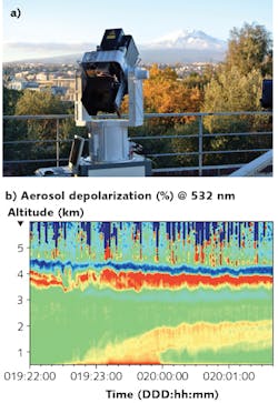
"The agriculture industry is using lidar to map terrains and to guide farmers on the selective distribution of fertilizers and pesticides. In biology and conservation, lidar monitors forest canopy heights or deforestation. The military uses lidar for autonomous vehicle and drone guidance, for identifying possible targets, and for tactical precision mapping. And, in the mining industry, lidars map excavated areas and determine volume removal," says Shawn Smith, U.S. West Coast sales manager for RPMC Lasers (O'Fallon, MO). "For surveying, lidar maps buildings and surrounding areas for future development, and atmospheric lidar systems map the 3D distribution of aerosols and molecules to characterize everything from pollution to clouds, wind, and even volcanic emissions [see Fig. 1]."
Lidar systems illuminate a target area or scene with pulsed laser light and measure how long it takes for reflected signals to be returned to a receiver. A lidar system includes a laser source or transmitter, a sensitive photodetector or receiver, synchronization and data processing electronics, and either motion-control equipment or solid-state microelectromechanical systems (MEMS)-based components for precise laser scanning to create 3D maps and/or proximity data.
Among these required components, Smith reminds us that the laser itself contributes to overall system performance. "The laser beam quality and divergence, for example, is responsible for the lateral resolution [x, y] of mapping lidars, while short pulse duration and timing jitter are responsible for the longitudinal accuracy [z]," Smith says. "Pulse energy is the key parameter to attain long ranges, while high pulse repetition rates allow faster scanning and high data throughput."
Performance considerations
"High-peak-power (tens of kilowatts to tens of megawatts) pulsed (nanosecond realm) solid-state lasers have been used in lidar applications for decades," Smith says. "Size and weight, cost, power consumption, liquid cooling, sensitivity to shock and vibrations, and harsh environments have limited the diffusion of lidar instruments in mobile, airborne, and space applications. But companies like Bright Solutions [Pavia, Italy] have recently developed a new generation of high-peak-power, sub-nanosecond, air- or conduction-cooled, Q-switched solid-state lasers that remove these limitations and offer a wide range of laser wavelengths from the ultraviolet (UV) to the near-infrared (near-IR)."
For airborne topographic mapping, a wavelength around 1 µm is typically used, in which case the beam is expanded large enough to be considered eye-safe. For bathymetry (high-resolution mapping of the sea bottom and coastal areas), a high-energy, frequency-doubled 532 nm laser source is often used, as the green wavelength represents the best compromise between high transmission in pure water and limited backscattering from submarine particulates.
Often, Smith says, the 532 nm to 1 µm wavelengths have benefits in terms of cost and energy consumption, but the need to reach relatively long ranges can easily lead to increased laser power over the limit of Class 1 laser safety. In such a case, laser emission can be hazardous to the eye if the beam is not expanded to an acceptable diameter (thus increasing the system size) to make it comply with eye-safe regulations.
Intrinsically eye-safe lasers are becoming more and more popular in high-performance compact lidar meant for civil and commercial applications. Among eye-safe wavelengths, IR lasers emitting around 1.5 µm are often the choice when solid bodies need to be detected as in topography mapping and obstacle avoidance. In fact, the atmosphere is very transparent and detectors are very efficient at 1.5 µm. Alternatively, UV wavelengths around 355 nm or shorter are the best choice for eye-safe atmospheric lidar systems, where relatively high backscattering coefficients from the atmospheric particulate are desired.
Beyond wavelength considerations, what about pulse duration? "Ideally," Smith adds, "lidar designers would like to reach millimeter-to-centimeter longitudinal measurement resolution, so short pulse durations should be considered. Nevertheless, very short pulses—on the order of a few picoseconds—would cause the laser spectrum and the receiver bandwidth to broaden, thus worsening signal-to-noise ratio." On the other hand, Smith adds that pulses longer than 1 ns would result in lower noise but poorer resolution, making pulse durations on the order of a few-hundred picoseconds (or sub-nanosecond) the best compromise for high longitudinal accuracy and signal-to-noise ratio.
To demonstrate that one size doesn't fit all when it comes to lasers for lidar, let's explore two very different applications—autonomous vehicles and forest canopy mapping.
Autonomous vehicle lidar
According to a recent survey from ABI Research (Oyster Bay, NY), the number of devices sold for automotive vehicles should reach 69 million units in 2026.1 As explained by Frédéric Chiquet, R&D manager Guillaume Canat, and CEO Marc le Flohic of Keopsys Group (Lannion, France), there are two main types of autonomous vehicle lidar systems: 3D flash lidar and scanning lidar.
Flash lidar uses a wide-angle-emitting source and wide-angle optics (a fisheye lens, for example) to focus backscattered light acquired during a single emission onto a matrix detector to obtain all the time-of-flight (TOF) data needed to model the area surrounding a vehicle. Conversely, scanning lidar addresses the 3D environment line by line; light is sequentially emitted in each direction and the corresponding echoes are detected one by one by the detector. The eye-safe laser source must operate in pulsed mode, be powerful enough to detect a pedestrian wearing dark clothes at 100 m, operate from -40 to 85°C, and emit pulses compatible with a measurement distance accuracy of 10 cm.
While many lidar sources are laser-diode-based, uncooled fiber lasers are also used and offer many advantages over pulsed laser diodes, including the ability to have their high-power beams split and routed to multiple sensor locations using optical fiber (see Fig. 2). Using a master oscillator power amplifier (MOPA) architecture, a typical 1550 nm lidar fiber laser has pulse repetition rates of 5 to 250 kHz at power levels from 10 to 15 kW and 200 to 300 W, respectively.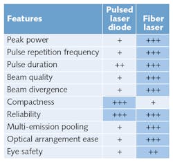
The pulsed laser diodes dedicated to autonomous cars are hybrid devices. A laser chip is mounted with capacitors that are triggered by a MOSFET transistor. Each time that the transistor gate is opened, the electric charge accumulated in the capacitors is discharged into the chip, which emits the optical pulse. But although this type of source is cost-effective, as its 905 nm output is easily detected by silicon detectors rather than expensive 1550 nm InGaAs photodiodes, laser diodes have limited pulse repetition rate and lower peak power, and are limited by overheating effects.
Laser diode sources for 3D flash lidar are based on diode stack technology, with several edge-emitting bars assembled into a vertical stack, with each layer separated by a thin heatsink to limit internal overheating. Unfortunately, non-coherent addition of the stacks creates high output power that often fails to meet Class 1 eye-safe requirements. And while vertical-cavity surface-emitting lasers represent a more cost-effective alternative to stacks, their weaker output power limits their use to shorter-range TOF applications.
Forest canopy mapping lidar
Researchers Supriya Chakrabarti, Timothy Cook, Kuravi Hewawasam, and Glenn Howe in the Lowell Center for Space Science and Technology (LoCSST) at the University of Massachusetts, Lowell, as well as colleagues from the University of Massachusetts, Boston and Boston University, have developed and field-tested a new terrestrial laser scanning lidar instrument built for the purpose of recording and retrieving the 3D structure of forest vegetation (see Fig. 3).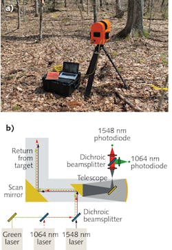
This Dual-Wavelength Echidna Lidar (DWEL) uses the differential reflectances of vegetation targets as observed from simultaneous laser pulses—one in the shortwave-infrared (SWIR) range and the others in the near-IR region—to characterize forest structure by distinguishing between leaves and trunks at an angular resolution as fine as 1 mrad.2,3
Based on Echidna laser scanning technology patented by Australia's Commonwealth Scientific and Industrial Research Organization (CSIRO), DWEL uses a rapidly rotating zenithal scan mirror and a slowly rotating azimuthal platform to provide full coverage of the angular scan space, with a 6 mm collimated beam diverging at 1.25, 2.5, or 5 mrad. The resulting field of view spans 360° in azimuth angle and ±117° in elevation angle. This full-waveform (as distinct from first-return) lidar completes a full-hemisphere scan by rotating 180° in azimuth in approximately 36 minutes in its standard resolution mode (2 mrad).
Including a green laser that allows the operator to visualize the beam direction, DWEL quantifies vegetation structure for environmental applications using the principle that leaves and other water-containing materials found in the forest absorb more strongly in SWIR (1548 nm) than near-IR (1064 nm), allowing the return signals of leaves to be separated from those of trunks, branches, and other dry materials in the forest (see Fig. 4).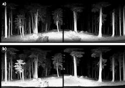
Nominal laser pulse length, 5 ns full width at half maximum (FWHM), is specified to provide a full description of return pulse shapes as digitized at 2 GHz. Full-waveform recording allows detection of multiple targets out to 100 m from the scanner. Pulse energy of 0.6 µJ provides a good signal-to-noise ratio while maintaining eye safety criteria. A dark Lambertian target inside the instrument housing is used for calibration with each scan mirror rotation.
Return signals are collected by a 10-cm-diameter Newtonian telescope, where the beams are chromatically separated and out-of-band wavelengths are eliminated using narrow bandpass interference filters. Return signals from each laser are detected by a pair of detector-amplifiers using InGaAs photodiodes.
The power of DWEL over most other lidar systems is its two-wavelength vegetation discrimination capability: leaves, which contain more moisture than woody material, appear darker in the 1548 channel compared to the 1064 channel. For this particular lidar task, as in all others regardless of industry, the laser itself is critical to satisfying the unique performance requirements of the application at hand.
REFERENCES
1. See https://goo.gl/Fs4VDH.
2. E. S. Douglas et al., IEEE Geosci. Remote Sens. Mag. (2015); doi:10.1109/LGRS.2014.2361812.
3. G. A. Howe et al., J. Appl. Remote Sens., 9, 095979 (2015).
About the Author

Gail Overton
Senior Editor (2004-2020)
Gail has more than 30 years of engineering, marketing, product management, and editorial experience in the photonics and optical communications industry. Before joining the staff at Laser Focus World in 2004, she held many product management and product marketing roles in the fiber-optics industry, most notably at Hughes (El Segundo, CA), GTE Labs (Waltham, MA), Corning (Corning, NY), Photon Kinetics (Beaverton, OR), and Newport Corporation (Irvine, CA). During her marketing career, Gail published articles in WDM Solutions and Sensors magazine and traveled internationally to conduct product and sales training. Gail received her BS degree in physics, with an emphasis in optics, from San Diego State University in San Diego, CA in May 1986.