Lidar: A photonics guide to the autonomous vehicle market
Advances in sensor technology, imaging, radar, light detection and ranging (lidar), electronics, and artificial intelligence have enabled dozens of advanced driver assistance systems (ADAS), including collision avoidance, blindspot monitoring, lane departure warning, or park assist. Synchronizing the operation of such systems through sensor fusion allows fully autonomous or self-driving vehicles to monitor their surroundings and warn drivers of potential road hazards, or even take evasive actions independent of the driver to prevent collision.
Autonomous vehicles must also differentiate and recognize objects ahead at high-speed conditions. Using distance-gauging technology, these self-driving cars must rapidly construct a three-dimensional (3D) map up to a distance of about 100 m, as well as create high-angular-resolution imagery at distances up to 250 m. And if the driver is not present, the artificial intelligence of the vehicle must make optimal decisions.
One of several basic approaches for this task measures round-trip time of flight (ToF) of a pulse of energy traveling from the autonomous vehicle to the target and back to the vehicle. Distance to the reflection point can be calculated when one knows the speed of the pulse through the air-a pulse that can be ultrasound (sonar), radio wave (radar), or light (lidar).
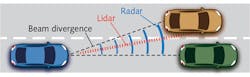
Of these three ToF techniques, lidar is the best choice to provide higher-angular-resolution imagery because its smaller diffraction (beam divergence) allows better recognition of adjacent objects compared to radar (see Fig. 1). This higher-angular-resolution is especially important at high speed to provide enough time to respond to a potential hazard such as head-on collision.
Laser source selection
In ToF lidar, a laser emits a pulse of light of duration τ that activates the internal clock in a timing circuit at the instant of emission (see Fig. 2). The reflected light pulse from the target reaches a photodetector, producing an electrical output that deactivates the clock. This electronically measured round-trip ToF Δt allows calculation of the distance R to the reflection point.
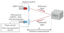
If the laser and photodetector are practically at the same location, the distance is given by

where c is the speed of light in vacuum and n is the index of refraction of the propagation medium (for air, approximately 1). Two factors affect the distance resolution ΔR: the uncertainty δΔt in measuring Δt and the spatial width w of the pulse (w = cτ), if the diameter of the laser spot is larger than the size of the target feature to be resolved.
The first factor implies ΔR = ½ cδΔt, whereas the second implies ΔR = ½ w = ½ cτ. If the distance is to be measured with a resolution of 5 cm, the above relations separately imply that δΔt is approximately 300 ps and τ is approximately 300 ps. Time-of-flight lidar requires photodetectors and detection electronics with small time jitter (the main contributor to δΔt) and lasers capable of emitting short-duration pulses, such as relatively expensive picosecond lasers. A laser in a typical automotive lidar system produces pulses of about 4 ns duration, so minimal beam divergence is essential.
One of the most critical choices for automotive lidar system designers is the light wavelength. Several factors constrain this choice: safety to human vision, interaction with the atmosphere, availability of lasers, and availability of photodetectors.
The two most popular wavelengths are 905 and 1550 nm, with the primary advantage of 905 nm being that silicon absorbs photons at this wavelength and silicon-based photodetectors are generally less expensive than the indium gallium arsenide (InGaAs) infrared (IR) photodetectors needed to detect 1550 nm light. However, the higher human-vision safety of 1550 nm allows the use of lasers with a larger radiant energy per pulse-an important factor in the photon budget.
Atmospheric attenuation (under all weather conditions), scattering from airborne particles, and reflectance from target surfaces are wavelength-dependent. This is a complex issue for automotive lidar because of the myriad of possible weather conditions and types of reflecting surfaces. Under most realistic settings, loss of light at 905 nm is less because water absorption is stronger at 1550 nm than at 905 nm.1
Photon detection options
Only a small fraction of photons emitted in a pulse ever reach the active area of the photodetector. If the atmospheric attenuation does not vary along the pulse's path, the beam divergence of the laser light is negligible, the illumination spot is smaller than the target, the angle of incidence is zero, and the reflection is Lambertian, then the optical received peak power P(R) is:
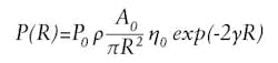
where P0 is the optical peak power of the emitted laser pulse, ρ is the reflectivity of the target, A0 is the receiver's aperture area, η0 is the detection optics' spectral transmission, and γ is the atmospheric extinction coefficient.
This equation shows that the received power rapidly decreases with increasing distance R. For a reasonable choice of the parameters and R=100 m, the number of returning photons on the detector's active area is on the order of a few hundred to a few thousand from the more than 1020 typically emitted. These photons compete for detection with background photons carrying no useful information.
Using a narrowband filter can reduce the amount of background light reaching the detector, but the amount cannot be reduced to zero. The effect of the background is the reduction of the detection dynamic range and higher noise (background photon shot noise). It's noteworthy that the terrestrial solar irradiance under typical conditions is less at 1550 nm than at 905 nm.
Creating a 3D map in a full 360° × 20° strip surrounding a car requires a raster-scanned laser beam or multiple beams, or flooding the scene with light and gathering a point cloud of data returns. The former approach is known as scanning lidar and the latter as flash lidar.
There are several approaches to scanning lidar. In the first, exemplified by Velodyne (San Jose, CA), the roof-mounted lidar platform rotates at 300-900 rpm while emitting pulses from 64 905 nm laser diodes. Each beam has a dedicated avalanche photodiode (APD) detector. A similar approach uses a rotating multi-faceted mirror with each facet at a slightly different tilt angle to steer a single beam of pulses in different azimuthal and declinational angles. The moving parts in both designs represent a failure risk in mechanically rough driving environments.
The second, more compact approach to scanning lidar uses a tiny microelectromechanical systems (MEMS) mirror to electrically steer a beam or beams in a 2D orientation. Although technically there are still moving parts (oscillating mirrors), the amplitude of the oscillation is small and the frequency is high enough to prevent mechanical resonances between the MEMS mirror and the car. However, the confined geometry of the mirror constrains its oscillation amplitude, which translates into limited field of view-a disadvantage of this MEMS approach. Nevertheless, this method is gaining interest because of its low cost and proven technology.
Optical phased array (OPA) technology, the third competing scanning lidar technique, is gaining popularity for its reliable, "no-moving-parts" design. It consists of arrays of optical antenna elements that are equally illuminated by coherent light. Beam steering is achieved by independently controlling the phase and amplitude of the re-emitted light by each element, and far-field interference produces a desired illumination pattern from a single beam to multiple beams. Unfortunately, light loss in the various OPA components restricts the usable range.
Flash lidar floods the scene with light, though the illumination region matches the field of view of the detector. The detector is an array of APDs at the focal plane of the detection optics. Each APD independently measures ToF to the target feature imaged on that APD. This is a truly "no-moving-parts" approach where the tangential resolution is limited by the pixel size of the 2D detector.
The major disadvantage of flash lidar, however, is photon budget: once the distance is more than a few tens of meters, the amount of returning light is too small for reliable detection. The budget can be improved at the expense of tangential resolution if instead of flooding the scene with photons, structured light-a grid of points-illuminates it. Vertical-cavity surface-emitting lasers (VCSELs) make it possible to create projectors emitting thousands of beams simultaneously in different directions.
Beyond time-of-flight limitations
Time-of-flight lidar is susceptible to noise because of the weakness of the returned pulses and wide bandwidth of the detection electronics, and threshold triggering can produce errors in measurement of Δt. For these reasons, frequency-modulated continuous-wave (FMCW) lidar is an interesting alternative.
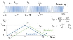
In FMCW radar, or chirped radar, the antenna continuously emits radio waves whose frequency is modulated-for example, linearly increasing from f0 to fmax over time T and then linearly decreasing from fmax to f0 over time T. If the wave reflects from a moving object at some distance and comes back to the emission point, its instantaneous frequency will differ from the one being emitted at that instant. The difference is because of two factors: the distance to the object and its relative radial velocity. One can electronically measure the frequency difference and simultaneously calculate the object's distance and velocity (see Fig. 3).
Inspired by chirped radar, FMCW lidar can be approached in different ways. In the simplest design, one can chirp-modulate the intensity of the beam of light that illuminates the target. This frequency is subject to the same laws (such as the Doppler effect) as the carrier frequency in FMCW radar. The returned light is detected by a photodetector to recover modulation frequency. The output is amplified and mixed in with the local oscillator allowing the measurement of frequency shift and from that, the calculation of distance to and speed of the target.
But FMCW lidar has some limitations. Compared to a ToF lidar, it requires more computational power and, therefore, is slower in generating a full 3D surround view. In addition, the accuracy of the measurements is very sensitive to linearity of the chirp ramp.
Although designing a functional lidar system is challenging, none of these challenges are insurmountable. As the research continues, we are getting closer to the time when the majority of cars driving off the assembly line will be fully autonomous.
REFERENCE
1. J. Wojtanowski et al., Opto-Electron. Rev., 22, 3, 183-190 (2014).
About the Author

Slawomir S. Piatek
Hamamatsu Corporation
Slawomir S. Piatek has been measuring proper motions of nearby galaxies using images obtained with the Hubble Space Telescope as a senior university lecturer of physics at New Jersey Institute of Technology. He has developed a photonics training program for engineers at Hamamatsu Corporation in New Jersey in the role of a science consultant. Also at Hamamatsu, he is involved in popularizing a SiPM as a novel photodetector by writing and lecturing about it, and by experimenting with the device. He earned a Ph.D. in Physics at Rutgers, the State University of New Jersey.