FIBEROPTIC ILLUMINATION: Cold light sharpens machine vision
In the industrial arena, the bulk of fiberoptic-illumination design work is custom. Most manufacturing lines are unique, according to Rob Robbins, machine-vision sales manager for the fiberoptics division at Schott North America (Auburn, NY), and manufacturers want illumination to fit into their unique construction. Custom-made light guides are often needed for a specific application even when “custom” is as simple as a 13.5 in. line rather than a 12 in. line, he said. A broad array of factors related to light sources as well as fibers play into customizing a design appropriately for a given application, and design approaches continue to evolve with the technology (see “Type of fiber depends on several factors,” p. 138).
Whether the lighting is provided through fibers or directly from the source, a major goal in machine vision is to provide illumination to enhance contrast for the machine-vision camera, which can differ dramatically from natural lighting or lighting suitable for human observers (see “Fiberoptic machine-vision illumination takes several forms,” p. 136). In factory environments, for instance, it’s necessary to provide enough luminance to overcome ambient lighting. A skylight might provide great natural illumination for the workers, but varying sky conditions would yield unacceptable variation in illumination for machine-vision applications, so an intense light source and perhaps a shrouded system would be required to block out the ambient effect.
Hot and cold light
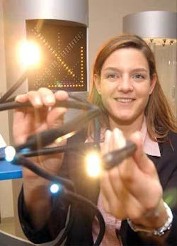
Halogen light sources provide more intensity than other sources, making them very useful for overcoming ambient light problems, and they have historically been the light source of choice for fiberoptic illumination in machine-vision applications. The primary disadvantage of halogen light sources, however, is radiated heat. Therefore, a key role for fiberoptics has been to provide “cold light” by separating heat-emitting light sources from the illuminated area, thereby eliminating or reducing damage or burn hazards to illuminated objects or people (see figure).
Plastic optical fiber is less expensive than glass and can offer more heat insulation because it attenuates the illumination more rapidly than glass, and the attenuation increases sharply in the infrared as well as the ultraviolet ends of the visible spectrum. But plastic fiber, which melts at 104°C, must also be protected from the heat of intense sources with glass optics at the launch end (see “LED-lit woven optical fiber takes on innovative applications,” p. 54).
While source intensity can improve performance, the associated heat also shortens the lifespan of the source and the system while also increasing maintenance costs. In addition, the intensity of all light sources tends to diminish with age. A vision system, therefore, can be set up properly at the beginning of its life but will deteriorate in performance as the light source dims with age.
To address this issue, Schott has designed an integrating sphere for halogen systems that measures intensity throughout system lifetime and uses a feedback loop to adjust system parameters. As Robbins points out, however, using a feedback system that optimizes these variables over the lifetime of the system obviously means that the light source can’t be operated at full intensity from day one.
Follow the LED
Due to recent major improvements in brightness and available color gamut, light-emitting diodes (LEDs) are emerging as important illumination sources for machine vision because they offer an order-of-magnitude greater life expectancy than halogen and emit much less heat. But use of LEDs still involves heat-management issues. A fan can keep a halogen source cool, but numerous LEDs tightly packed on a circuit board also need heat sinks as well as blowing air or flowing liquid to cool them. Metal circuit boards, which are used to conduct the heat away from the chips, can also warp due to the heat, thereby changing the light source distribution once again.
Incandescent technology (particularly high-intensity-discharge lamps) still offers the primary illumination source for medical applications, but as LED brightness continues to approach incandescent levels, LEDs are becoming the preferred fiber-illumination sources for many industrial applications. This is particularly true in semiconductor and computer electronics where the need for fiberoptics to direct bright light into small spaces for complex electronic assembly tasks (of the kind that produce LEDs in the first place) continues to increase rapidly.
Improving LED brightness is also allowing the cold-source benefits of fiber to be combined with the long life of LEDs for an increasing range of applications. Schott introduced LED illumination coupled to fiber sources this year. But even now, as Robbins points out, to replace a halogen source with LED illumination the application needs to be one in which the full intensity of the halogen lamp was not being used. Multiple LEDs can provide more light, but coupling them into fiber presents more of an optical challenge.
LED fiber illumination works where you don’t need the intensity of halogen and where you could not accommodate direct LED lighting in a line or ring configuration because of space and heating constraints, Robbins said. Halogen can be as much as ten times brighter than LED illumination, but with new LED light engines, the difference factor can be as small as one third.
With halogen, a single light source is focused into the end of a fiberoptic bundle. The fibers are cut off, ground, and polished to accept light across a plane surface. And the light source is designed to optimize the light intensity at the input end of the fiber bundle. Nevertheless, a characteristic defect of light-bulb illumination applied to machine-vision applications is a dark spot in the center, which is addressed by randomization of fiber arrangement within a bundle to ensure that no dark spots appear at the output end.
LED illumination also presents imperfections due to dark boundaries between adjacent LED chips, making it necessary to randomize the fibers. A diffusing filter on the input fiber end is sufficient to diffuse the incident light for some applications, but for others, the more expensive route of fiber randomization is necessary.
The LED manufacturers are chasing halogen capabilities, Robbins said. You can see this in products for table lamps at home. LEDs are still cost prohibitive right now, but that will change. The challenge is to get the intensity up while getting the heat down and maintaining the life expectancy.
Fiberoptic machine-vision illumination takes several forms
There are essentially four main approaches to fiberoptic illumination for machine vision: light lines, ring lights, spot lights, and back lights. And then there are variations on those, such as the diffuse lighting that can be obtained by shining ring lights into a reflective dome. The latter provides diffuse lighting (cloudy-day illumination) that can be useful for looking at paint on a surface. If the lighting were too bright and direct, all that you would see would be the reflected sheen.
Light lines are typically used in web applications or where discrete parts are moving through assembly operations, such as glass float lines; fabric webs, in which the translucent fabric is backlit to enable observation using a line scan camera on the front side; steel production, in which the camera view is illuminated with reflected light from the opaque surface; and numerous other web-based industries such as paper, rubber, printing.
Despite the utility of light lines, the most common fiber lighting is the ring light, which can be used for bright-field or dark-field illumination. A ring of fibers emits light from all around the camera along a conical trajectory to converge and provide even illumination at a range of working distances, which are defined in the ring-light specifications (see figure). In light-field illumination, the angle of incidence is normal to the illuminated object. In dark-field illumination, a low angle of incidence is used to intentionally create shadows and bring out surface texture, which is good for detecting flaws, such as lumps in a coat of paint. Ring lights are often used for two-dimensional vision applications, looking at a part, say, for presence or absence, dimensional gauging, text/optical character recognition, pattern matching or looking for surface flaws.
Two-dimensional resolution is not as great as with line-scan cameras, which also clock at a faster rate because they do not require the additional image processing of two-dimensional imaging. Another lighting approach is the single bundle or point used to illuminate a spot, which is particularly useful for illuminating small isolated areas, such as on a circuit board to read only specific characters in a specific spot.
Type of fiber depends on several factors
The type of fiber used depends upon the application. Several factors should be considered when choosing a fiber:
- The wavelength of light that needs to be carried and whether optimal transmission of either a broad wavelength spectrum or a specific area of the spectrum is desired. For the visual range, the challenge is to maximize transmission efficiency.
- Glass issues include fragility and fiber diameter. Thicker glass is more durable but doesn’t bend as well, which also makes the glass more fragile. For the IR and UV ranges glass materials required are generally quartz or fused silica. Plastic is less expensive and less transmissive.
- Flexibility and bend radius.
- Numerical aperture (NA), which depends on the physics of internal reflection inherent in the glass and cladding used.
- Bundling issues can arise depending on the wavelength of the light source. UV light can deteriorate the epoxy used to hold a bundle together. Ways of dealing with this include using heat to melt and fuse the tip material, which also enhances fiber tolerance to heat. Alternatively, high pressure can change the shape of the fibers from round to hexagonal, enabling them to fit together better and minimizing interstitials, while also making the bundle more heat resistant. Placing IR or UV filters on the light sources is a more economical alternative, but some applications require more expensive heat or pressure processes.
About the Author
Hassaun A. Jones-Bey
Senior Editor and Freelance Writer
Hassaun A. Jones-Bey was a senior editor and then freelance writer for Laser Focus World.