High-power, low-SMILE vertical stack diode laser bars enable better laser cladding
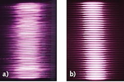
High-power diode lasers play a major role in materials processing. Compared to conventional carbon dioxide (CO2) lasers, high-power direct-diode laser sources have great advantages, such as high efficiency, low cost, wavelength versatility, and high reliability. High-power diode lasers, with a 9xx nm wavelength much shorter than that of CO2 lasers, increases the absorption of the metal surface and improves the melting efficiency.1 However, the large SMILE effect, of which the emitters are vertically displaced in a laser diode bar, causes poor output beam quality.2 Laser diode array bowing in the fast axis increases the geometrical line width of the output line when creating a line by collimating and focusing an emitting light from a laser array in the fast axis.3 The poor output beam quality of direct diode lasers is a large obstacle in industrial applications (see Fig. 1).4, 5
As reported here, a symmetrical structure was designed by bonding two submounts on the top and bottom of the heatsink to reduce the SMILE effect by balancing the packaging-induced stress. The 95% measured SMILE value in volume production was less than 2 µm. Low-SMILE vertical stacks made of 32 laser bars, each bonded on a microchannel cooler (MCC), were designed and characterized. A 2 × 20 mm2 rectangular beam of 6 kW continuous-wave (CW) output power with a beam uniformity of 90% was demonstrated.
This kind of rectangular high-power laser beam from low-SMILE laser bars is widely used in laser cladding applications. By adding cladding material (composite metal powder) on the surface of the metal substrate, laser cladding uses a high-energy-density and high-uniformity laser beam to melt cladding material together with the metal substrate surface to form a liquid metal molten pool, which is naturally cooled and solidified to form a metallurgically bonded material cladding layer on the substrate surface. This new material cladding layer can significantly improve the wear resistance, corrosion resistance, heat resistance, oxidation resistance, and electrical properties of the substrate material surface to achieve the purpose of surface modification or repair, meet the specific performance requirements of the material surface, and save materials cost.
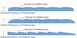
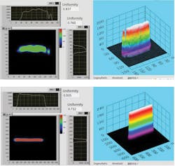
Laser cladding process efficiency is greatly affected by the uniformity of the laser beam (including the SMILE of the laser source). Uniform laser beam energy distribution can lead to a good processing pool. Given a standard-thickness cladding layer, a high-uniformity laser beam can achieve smooth surface cladding through a lower amount of overlap. However, when using a laser beam with high SMILE, more overlaps are needed to make up for cladding layer thickness differences caused by nonuniform laser beam energy.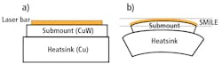
Low-SMILE laser bar based on DMCC
The traditional laser device based on a MCC is built with a laser bar bonded on a submount, such as copper/tungsten (CuW), and then on a MCC with a hard solder like gold/tin (AuSn), as shown in Figure 2a (called HMCC). Due to the coefficient of thermal expansion (CTE) mismatch between the laser bar (typical GaAs with 6.5 ppm/K) and MCC (typical copper with 16.5 ppm/K), a CuW submount with a CTE closely matched to that of a laser bar is used to minimize the packaging-induced stress on the laser bar after bonding.6 During cooldown from 287°C (AuSn melting temperature) to 25°C (room temperature), copper shrinks more than CuW because the CTE of copper is larger than that of CuW, resulting in a bowed laser bar/CuW/MCC for an asymmetrical structure (see Fig. 2b). Normally, the SMILE value of HMCC is almost 10–15 μm; the simulation results using finite element analysis and the experimental results will be shown later.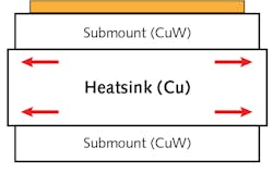
![FIGURE 4. Simulated SMILE shape of a 1 cm laser bar bonded on HMCC and DMCC [7].](https://img.laserfocusworld.com/files/base/ebm/lfw/image/2021/01/2101LFW_wei_z4.60006c687cc77.png?auto=format,compress&fit=max&q=45?w=250&width=250)
![FIGURE 5. The measured SMILE shape and value of a 1 cm laser bar, each bonded on HMCC (12 μm) and DMCC (1 μm). [6, 7]](https://img.laserfocusworld.com/files/base/ebm/lfw/image/2021/01/2101LFW_wei_z5.60004f0c972c3.png?auto=format,compress&fit=max&q=45?w=250&width=250)
Vertical stack with 32-bar DMCCs
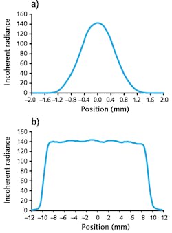
To get a higher power, a vertical stack of 32 DMCCs was used to get the 6 kW output power at 200 A injection current. Test results for the 32-bar vertical stack are shown in Figure 6. A 2 × 20 mm2 rectangular beam was built with a 32-bar vertical stack (SMILE <2 μm) to produce 6 kW CW mode output power with a beam uniformity of more than 90% (see Fig. 7). The simulated intensity profile of the 32-bar vertical stack in the fast and slow axes are shown in Figures 8a and 8b, respectively. A 2 × 20 mm2 rectangular spot has many functions in materials processing, such as high-throughput scanning along the fast axis, due to the long edge of the spot. A flat-top spot guarantees the uniformity of the treated surface and is also perfect for obtaining a smooth brazing seam because the spot is narrow along the fast-axis direction.
REFERENCES
1. H. Zhu et al., Opt. Laser Technol., 76, 101–105 (2016).
2. H. Zhang et al., Appl. Opt., 57, 28, 8407–8411 (2018).
3. C. Zah et al., Proc. HPD 2017, 9–10 (2017); doi:10.1109/hpd.2017.8261079.
4. L. Li, Opt. Lasers Eng., 34, 4–6, 231–253 (2000).
5. G. C. Rodrigues et al., Opt. Lasers Eng., 61, 31–38 (2014).
6. J. L. Hostetler et al., Proc. SPIE, 6456, 645602 (Feb. 2007).
7. H. Zhang et al., Opt. Eng., 57, 3, 036115 (2018).