Photometric stereo techniques analyze reflections to improve image contrast
ARNAUD LINA, PIERANTONIO BORIERO, and KATIA OSTROWSKI
A key challenge in machine vision applications is generating images with sufficient contrast to reliably discern objects or features of interest—such as defects or symbols—from the general background. Such features can rise from or recess into a surface, or have a different coating or texture compared to the rest of the surface while still having the same appearance, color-wise, as the rest of the surface.
The challenge of generating enough contrast in these situations is formidable. However, photometric stereo computational imaging techniques combine images obtained with varying directional illumination and analyze the resulting reflections from those images are an effective means of producing images with enhanced contrast.
Photometric stereo theory
Consider a uniformly colored object. The shading and shadows on its surface typically change as a result of the orientation of the surface in relation to a light source, as well as the properties of the incoming light. As such, it is well known that not every detail of an object’s surface is noticeable in a single image.
Photometric stereo is a computational imaging technique for separating the 3D shape of an object from its 2D texture. Once the 2D texture (such as a pebbled or rough surface) has been removed from the 3D surface, photometric stereo analysis can determine the surface curvature of an object and identify small defects that may otherwise be undetectable using conventional image-processing techniques.
Basically, photometric stereo assesses the surface normals of an object through observation of that object under different lighting conditions but viewed from the same position, by exploiting variations in intensity of the lighting conditions.1
During this process, it is assumed that the camera does not move in relation to the illumination and no other camera settings are changed while grabbing the series of images. The resulting images are used together to create a single composite image, in which the resulting radiometric constraint makes it possible to obtain local estimates of both surface orientation and surface curvature.1
Photometric stereo imaging aims to illustrate the surface orientation and curvature of an object based on data derived from a known combination of reflectance and lighting in multiple images—an invaluable process for machine vision applications with tight quality control and assurance demands, such as on production or manufacturing lines.
Lambert first outlined the concept of perfect light diffusion or “Lambertian reflectance” in his 1760 book Photometria. A Lambertian surface is considered the ideal matte surface, wherein surface radiation is uniform in all directions regardless of the observer’s angle of view.2 Woodham based his theory of photometric stereo on Lambert’s work; early research constrained the surface reflectance model to Lambertian surfaces, an assumption that simplifies calculations considerably.
Photometric stereo theory was subsequently expanded to encompass non-Lambertian reflectance models, including those from Phong, Torrance-Sparrow, and Ward—and more recent studies are expanding the potential of the technique.3 The 3D elevation of the surface in question can also be retrieved from the surface orientation—however, stereo-photometry-based 3D reconstruction is typically limited in resolution and is sensitive to the object surface properties and thus very difficult to put to practical use.From theory to implementation
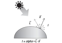
Photometric stereo registration operations use material reflectance properties and the surface curvature of objects when calculating the resulting enhanced image based on Lambertian (matte, diffuse) surfaces. In this case, the diffuse reflected intensity I is proportional to the angle between the incident light direction L and the surface normal n (see Fig. 1). This proportion is driven by the albedo reflectivity alpha that constitutes Lambert’s Cosine Law.4 The albedo of a surface is the fraction of the incident sunlight that the surface reflects.5
Therefore, the unknowns to be determined in this example are the surface normal n and the albedo reflectivity alpha. The light is considered distant and all rays of light are considered parallel. Given the L directions within the illumination configuration (one per light source), the directions L are thus known in advance.
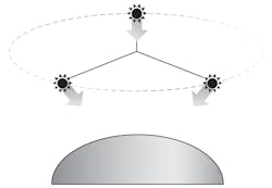
Determining these unknowns begins with acquiring images of an object for a minimum of three non-coplanar light directions, wherein each image corresponds to a specific light direction (see Fig. 2). Using these unique directional lighting images, the albedo values and normals can be calculated for each point of the object.
Information about the surface normals derived from photometric stereo analysis can reveal important information about the objects’ surface, such as the presence of surface irregularities (like embossed or engraved features, scratches, or indentations) that can occur despite the expectation that the surface is smooth.
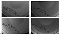
Although the photometric stereo technique requires at least three images to determine the normals in a given scene, more directional lighting sources than this minimal number are typically used to reduce noise inherent in the imaging process and to generate more accurate images.6, 7 The redundancy provided by multiple images leads to better analysis results. Typically, in practice, a minimum of four images are needed (see Fig. 3).8Illumination considerations and calculations
The distant light assumption of parallel illumination rays is reasonable in many vision applications where there has been careful selection of the illumination system regarding dimension of the scene. Appropriate lighting tools, such as segment bars and ring lights like those available from Advanced Illumination (Rochester, VT), CCS (Boston, MA), or Smart Vision Lights (Muskegon, MI), among others, can easily be found on the market. For companies like Matrox Imaging (Montreal, QC, Canada) that offer machine vision software with photometric stereo tools, these purpose-built lights facilitate integration and setup.
When lighting directions and intensities are known, photometric stereo can be solved as a linear system. Lighting positioning can be provided based on the illumination setup geometry or it can be calibrated from the images using a specular reflective sphere, for example (see Fig. 4).
When the illumination details are unknown, a much harder problem must be solved—namely, uncalibrated photometric stereo. While solutions exist for calculating photometric stereo in these instances, it is worth noting that without knowing the lighting direction, it is worth noting that uncalibrated solutions are more sensitive to acquisition conditions and can suffer from poor repeatability.9
Static object applications
The scene or object undergoing photometric stereo registration is meant to be stationary, although analysis can be performed on moving objects as detailed in the next section. Regardless of how the results are calculated, the output of photometric stereo analysis provides the estimated normal of the surface object as well as the albedo results.
The albedo result provides the estimated albedo of the surface material as a percentage of the reflected intensity. Changes in surface reflectance—from shiny to dull—should be apparent in an albedo image result. These changes in diffuse reflectivity may indicate a change in material properties that leads to enhanced visual contrast (see Fig. 5). Enhanced contrast can simplify—and outright enable—subsequent image analysis.
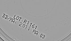
The second result is the calculation of the surface normals. Rapid change of the surface normals can indicate the presence of defects such as cracks, scratches, or dents. Multiple results can be derived from surface normals, including local surface curvatures. These curvature results may prove easier to analyze than the field of normal vectors, as they generally enhance local variations of the normal directions, such as protruding marks or a puncture in an otherwise flat surface. For example, printed text no longer obscures an embossed symbol (see Fig. 6).
Changes in curvatures may be sensitive to signal dynamic and noise, and subsequently difficult to analyze. Other metrics derived from the normals can be used to enhance local variations.
Moving object applications
Though photometric stereo is ideally performed on a stationary object or scene, it is possible to perform the analysis on moving objects, such as those on a conveyor belt. To account for the objects’ motion, images must be realigned to compensate for an object’s location at the time another image is taken. To this end, additional leading and trailing images should be taken with full illumination and then analyzed to establish the object’s displacement.10
The images bookended by these additional images (the photometric stereo source images taken with directional lighting) are then translated so that the object is at the same position in each image. Images are captured by cameras operating at a sufficiently high speed and the small degree of displacement also minimizes perspective distortion and parallax errors.
By using a known combination of lighting and reflectance in multiple images to analyze surface curvatures and highlight variations in the surface normals indicative of embossed or engraved features such as serial numbers, or defects such as cracks, scratches, or dents, photometric stereo imaging can be a powerful tool in the machine vision industry, offering a cost-effective manner to produce and analyze images of local features.
REFERENCES
1. R. J. Woodham, Opt. Eng., 19, 1, 139–144 (Jan/Feb. 1980); see http://bit.ly/photometricref1.
2. E. Angel and D. Shreiner, Interactive Computer Graphics: A top-down approach with shader-based OpenGL, Addison-Wesley, Boston, MA (2012).
3. J. Lim et al., Proc. ICCV’05, 2, 1635–1642, Beijing, China (Oct. 2005); see http://bit.ly/photometricref3.
4. See http://bit.ly/photometricref4.
5. See http://bit.ly/photometricref5.
6. See http://bit.ly/photometricref6.
7. R. J. Woodham, J. Opt. Soc. Am., 11, 11, 3050–3068 (1994); see http://bit.ly/photometricref7.
8. See http://bit.ly/photometricref8.
9. T. Papadhimitri and P. Favaro, Proc. BMVC 2014, Nottingham, England (2014); see http://bit.ly/photometricref9.
10. See http://bit.ly/photometricref10.
Arnaud Lina is director of research and innovation, Pierantonio Boriero is director of product management, and Katia Ostrowski is communications specialist, all at Matrox Imaging, Québec, QC, Canada; e-mail: [email protected]; www.matrox.com.
