Micrometer-scale precision: Error budgeting for high-throughput laser drilling systems
Achieving micrometer-scale spot size precision in high-speed laser drilling applications presents design challenges for machine builders whose goal is to create equipment that meets end-user requirements for production output volume and quality. Industries such as electronics and semiconductor packaging are creating a demand for smaller, more complex through-hole patterns—commonly known as “vias.” Achieving these smaller via tolerances requires a deep understanding of error sources that compound during the drilling process.
Various error sources contribute to overall system accuracy, and it is necessary to examine how their interaction impacts the overall tolerance of via position accuracy and via geometry tolerances in large substrates with thousands to millions of holes. These error sources can be attributed to the mechanical design of the part handling as well as the laser beam source, optics, and beam steering system used to perform the drilling operations.
Deconstructing the error budget: Sources and interactions
Error budgeting is the systematic process of identifying, quantifying, and tracking all error sources of a machine to predict the cumulative error at the functional point, where the laser meets the workpiece. For a multi-axis laser drilling system, these errors originate from two primary domains: the mechanical stages moving the part and the optics and scanner moving the laser beam. Second-order errors, derived from the motion profile’s dynamics (see Fig. 1) and the triggering of the laser once in position, also contribute to the overall error budget.
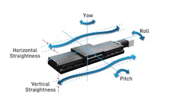
Mechanical motion errors. The servo-driven stages that move the workpiece or optics form the machine’s foundation, and their inherent geometric errors are a primary contributor to the error budget. Any axis of motion in a machine is subject to errors in all six degrees of freedom. For a single linear stage moving along the x-axis (see Fig. 2), these include three linear errors (positioning accuracy, horizontal straightness, and vertical straightness) and three angular errors (roll, pitch, and yaw). These parasitic motions, particularly the angular components, can create significant Abbé errors that displace the laser beam at the work surface, an effect that is magnified by the distance from the axis of motion to the workpiece.
Galvanometer scanner and optical errors. The galvanometer scanner, while incredibly fast and agile, brings its own set of errors. F-theta lenses, which are used to translate the scanner’s angular motion into a flat focal plane, are not perfect and introduce spatial nonlinearities known as pincushion or barrel distortion (see Fig. 3). Furthermore, the laser beam itself can be a source of instability. Thermal drift within the laser source or along the optical path can cause the focus to shift or the beam to wander over a long production run. Even environmental factors like dirty optical components can degrade performance by increasing the focal spot size or altering the beam's energy distribution, which directly impacts hole quality and consistency.
Error measurement and compensation
Before any motion occurs, the system components are measured and calibrated. These are considered first-order error sources and, without correction, prevent the laser from triggering in the correct location because they cannot be seen by the motion components’ feedback devices.
1D/2D stage calibration. Using laser interferometers, position errors of each stage at the desired functional workpoint are measured across their full travel. This data is used to generate calibration tables for each axis that are referenced in real time to correct not only for linear positioning errors but also for straightness, pitch, yaw, and inter-axis errors like nonorthogonality. This effectively makes the physical stage(s) behave like their ideal theoretical counterpart, automatically correcting for workpoint Abbé at the point of measurement as the stages move across travel.
Scanner calibration. Performing a “mark-and-measure” calibration enables accurate measurement of optical errors associated with the F-theta objective lens. The scanner is commanded to mark a precise grid of known locations. A high-resolution camera located within the system then measures the actual location of these marks and the difference is collected as position offsets for a calibration table stored within the motion controller. This calibration of the scanner compensates for F-theta lens distortion and other nonlinearities across the field of view (FOV).
It's also important to characterize how the laser spot size and shape vary across the FOV for the specific F-theta lens objective used to focus the laser beam, because this can influence process parameters. These spot size errors can also be measured as part of the “mark-and-measure” process and calibrated by changing the working distance of the lens dynamically to keep the spot in focus, as well as varying laser power to maintain consistent laser fluence.
Static calibration is essential, but cannot correct for second-order dynamic errors that occur during high-speed motion where the laser’s spot can shift due to tracking errors stemming from the mechanical system’s inertia. This is especially true during stage motion, because the mass of these stages is significant. In these cases, it’s best to leverage the laser scan head’s high dynamics to allow for higher throughput. Traditional drilling approaches, which involve the stage moving to a position, settling, and then letting the scanner work, are slow and introduce quality defects at the scanner’s FOV boundaries as it moves.
Infinite-field-of-view (IFOV) technology eliminates this limitation. It operates on a unified control architecture that synchronously manages the scanner’s high-frequency control loop (e.g., 200 kHz) and the stage’s servo loop (e.g., 20 kHz). Because IFOV uses live encoder feedback from the stages as a direct input to the scanner’s control loop, the scanner can dynamically and continuously adjust its trajectory to track and compensate for the stage’s actual position, effectively canceling out stage tracking errors in real time. The result is a single, seamless tool path that enables continuous “on-the-fly” processing over the entire workpiece and eliminates stitching errors.
Within a highly dynamic IFOV system, velocity is constantly changing. Firing the laser based on a fixed time interval would result in unevenly spaced vias. Position synchronized output (PSO) technology solves this by using the encoders’ real-time, combined IFOV position to trigger the laser at precise spatial intervals. This ensures each laser pulse or burst is placed on the workpiece with precision, regardless of motion speed variations, which is critical for maintaining accurate via pitch.
Validated approach to error budgeting
Understanding how these independent error sources combine is crucial. A simple summation of peak errors provides a “worst-case” value that is overly conservative and leads to unnecessarily expensive designs. A more practical and statistically valid method is to combine uncorrelated errors using the root sum square (RSS) approach.
The validity of this methodology was confirmed in a detailed study by William Land II and Scott Schmidt of Aerotech.1 They performed a series of high-precision measurements to meticulously quantify system performance. First, the underlying linear motor servo stages were calibrated using a two-dimensional (2D) laser interferometer system. This process created a correction map that removed static errors, including those induced by stage yaw and nonorthogonal alignment. The galvanometer scan head assembly was then calibrated independently using an iterative “mark-and-measure” technique to correct for its error contributions.
The quantified results from this testing provide a clear benchmark:
- The calibrated servo stages exhibited a residual vector sum error of 5.26 µm.
- The calibrated galvanometer system had a vector error of 2.06 µm.
Using the RSS method, the predicted combined error would be 5.262 µm (stage only) + 2.062 µm (scanner only) = 5.65 µm (RSS error of combined system). To verify this, a random combined motion grid test was executed, where both the stage and scanner moved simultaneously and opposingly to generate marks on a substrate. The empirically measured combined error from this dynamic test was 5.44 µm. The close correlation between the predicted and measured values provides a high degree of confidence that a well-constructed error budget can accurately forecast a machine’s baseline, quasi-static performance, which is the essential first step toward building a successful system.
Advanced control loop optimization
Even with a fully calibrated system using IFOV and PSO, ultimate performance can be limited by the responsiveness of the control system itself. Standard proportional-integral-derivative (PID) control loops, even when augmented with feed-forward gains, are typically tuned for a generic, “average” move profile. This single tuning profile represents a compromise.
The optimal control loop gains for a short, aggressive scanner move are fundamentally different from the optimal gains for a longer, smoother move. To extract maximum throughput, the system must accelerate, move, and settle at each target position in the absolute minimum time possible.
Advanced motion optimization software, such as Aerotech’s DrillOptimizer (see Fig. 3), uses iterative machine learning and reinforcement learning algorithms to achieve this. This process involves the following: characterizing the galvanometer system’s dynamic response to moves of different lengths and directions within the FOV; building a comprehensive library of optimal PID and feed-forward tuning parameters for every conceivable move; and during real-time operation, for each via-to-via move, the controller instantly fetches and applies the ideal set of control parameters for that specific move vector.
This move-specific optimization ensures that each move settles within the required stability window (e.g., ±2 µm) within the shortest possible time. This allows the laser to fire with zero move delay and pushes the physical hardware to its absolute performance limits and maximizes throughput beyond what a conventionally tuned system can achieve. Aerotech has combined tools that accomplish this into a software package called DrillOptimizer), which is part of our AeroscriptPlus libraries. Using these libraries, machine builders can integrate this type of powerful move and settle optimization directly into their machine’s human-machine interface (HMI) and add this complex optimization to every customer profile.
Takeaways for machine designers of laser drilling systems
The journey from a blank design to a machine capable of laser drilling vias is a multilayered process. It begins with a foundational error budget, meticulously constructed and validated by empirical data, to understand the system’s baseline accuracy. This accounting is then optimized with a comprehensive toolkit of compensation methods, from static 2D calibration of the stages to dynamic real-time error correction with IFOV and precise pulse placement with PSO. The final, crucial step is unlocking the hardware's ultimate potential through advanced, move-specific control loop optimization.
This integrated strategy makes it possible to meet the extreme demands of modern laser drilling. By understanding, accounting for, and actively compensating for every source of error at each stage in the process, it becomes possible to hold a micrometer-level stability window at thousands of locations per second, which turns a manufacturing challenge of immense scale into a high-throughput reality.
REFERENCE
- S. Schmidt and W. Land II, “Estimating combined servo and galvo motion accuracy,” Aerotech white paper (Dec. 2021); see www.aerotech.com/estimating-combined-servo-and-galvo-motion-accuracy.
About the Author
Bryan Germann
Bryan Germann is Aerotech’s product manager. He focuses on light manipulation products, including Aerotech’s AGV laser scan heads and associated Automation1 drives and software control features. He has hands-on experience designing and managing the production of high-precision motion control and automation machinery and products. Germann earned his bachelor’s and master’s degrees in mechanical engineering from the University of South Carolina. He holds 17 U.S. and international patents.

Eric Belski
Eric Belski is Aerotech’s laser applications laboratory manager. He leads the development of advanced precision automation and laser machining applications. Belski collaborates with laser technologists and researchers in order to address Aerotech customers’ most challenging laser applications. He has 10+ years’ professional experience in precision motion control and robotics—with roles in mechatronics research, systems engineering, and robotic system controls. Belski earned his bachelor’s and master’s degrees in mechanical engineering from the University of Pittsburgh.


