Optimizing laser cutting of Li-ion battery foils
Lithium-ion (Li-ion) batteries have become the energy storage medium of choice in a wide range of applications, from cell phones and laptop computers to electric vehicles (EVs). Each of these uses has specific needs in terms of battery characteristics and cost. For EVs, there are greater demands on properties like energy density, charging cycle time, operating temperature range, and mechanical durability than for batteries used in portable electronics. To meet their market requirements, EV manufacturers are putting great effort into improving both reliability and performance, while simultaneously reducing costs.
Achieving this objective has placed every aspect of battery manufacturing under close scrutiny. Of particular interest is electrode foil cutting, because this frequently represents a bottleneck in Li-ion battery production. As a result, speeding up foil cutting can reduce costs.
But cost and throughput improvements in electrode cutting processes must not come at the expense of quality. In particular, any new process cannot generate debris or cause thermal damage that might subsequently degrade battery performance or safety over time.
Ultrashort-pulse (USP) lasers have emerged as a technology that offers exactly the combination of cutting characteristics that battery manufacturers require, namely precision, minimal heat-affected zones, and reduced contamination. But one major challenge remains—throughput. For USP lasers to be deployed in high-volume battery manufacturing, cutting speeds must be maximized without sacrificing quality.
Li-ion battery production
Li‑ion batteries have a layered structure comprised of several elements: a cathode battery foil, an anode battery foil, a separator material, and an electrolyte. The battery foils consist of a metal substrate—typically copper for the anode and aluminum for the cathode—and an active material applied as a coating to both sides of the substrate.
These multilayer battery foils are typically fabricated using reel-to-reel processes (see Fig. 1). To start, the bare aluminum or copper current collector foil is coated, dried, and “calendered” (compressed between two hard rollers to achieve a specific thickness, density, and surface smoothness).
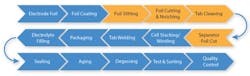
The end result of foil coating is a continuous, long sheet electrode rolled up into a “mother coil” the width of several electrodes, which is then cut into “daughter coils” that are each the approximate width of a finished electrode. This process is called “slitting.”
After additional cleaning steps, individual electrodes are cut from the daughter coils into their final shape. This shaping usually involves two distinct processes. One is a cut made perpendicular to the direction of reel travel to bring each electrode into its final size. The second is “notching,” which is a cut that forms a tab that will later be used for electrical connections in cell assembly and packaging.
Cutting processes
Slitting, cutting, and notching each have their own distinct requirements, and different cutting technologies can be used to perform them. The requirements for slitting are typically relaxed enough that it can be performed with mechanical rotary knives, although lasers are used by some manufacturers for the most sensitive materials.
Today, many manufacturers perform cutting and notching using die punching. But die punching is problematic because they are inflexible (fixed cutting shape), can generate edge burrs and inconsistent edge quality, and can cause foil wrinkling and coating delamination. Their biggest drawback is that mechanical die wear out quickly (~5,000 punch cycles), and replacing them causes equipment downtime and high consumables cost. Most battery makers are searching for alternative methods.
As a result, pulsed (nanosecond) fiber lasers, as well as other nanosecond and continuous-wave (CW) lasers, have found widespread use for cutting and notching. Fiber lasers are particularly well suited for cutting copper anodes because the high thermal conductivity of copper allows it to effectively dissipate the heating induced by fiber laser cutting.
But pulsed and CW fiber lasers cut using thermal cutting mechanisms that can introduce unwanted heating. The resulting melting, particle generation, and edge irregularity can degrade battery performance or safety—even with a copper-based anode.
This issue becomes more pronounced when cutting aluminum cathodes because of its lower thermal conductivity, which means more heat accumulates around the cut leading to a large heat-affected zone (HAZ). It can cause coating damage, and coating pullback—an area around the cut where the coating has receded away from the edge that leaves the bare foil exposed (see Fig. 2). Coating pullback creates several issues. First, it reduces the active area of the electrode, which directly lowers total storage capacity and reduces output power. It also increases the opportunity for electrical shunting to occur. This can cause internal short circuits, reduced reliability, thermal runaway, or fire.

Further, fiber laser cutting of aluminum is more prone to particulate (debris) generation, and also produces recast material and edge beads. While these problems can occur with copper, they are far less common. Contaminants may not be immediately visible but can interfere with later stages like stacking, tab welding, or electrolyte filling.
Another more subtle problem with most pulsed lasers impacts the notching process because it involves cutting a complex shape with several corners. The laser beam slows down when cutting corners due to the inertia of the scan mirrors controlling its position, which causes the pulses to overlap more (since the lasers typically operate at a fixed repetition rate). Avoiding this requires the ability to vary repetition rate on the fly, a feature typically called “pulse-on-demand.”
USP laser benefits
Any attempts to solve these problems using conventional mechanical or thermal methods inevitably involve tradeoffs between speed and quality, or between process cost and long-term battery reliability. But USP lasers (picosecond or femtosecond regime pulse widths) can avoid these tradeoffs because they use a fundamentally different mechanism for material removal.
There are two significant ways in which the USP laser/material interaction is unique. First, the very high peak powers generated in an ultrashort pulse excite nonlinear absorption in many materials. This can break molecular bonds directly and remove material through plasma formation, which results in highly efficient ablation processes.
The second way in which USP laser processing is distinct relates to the extremely short pulse durations. Their energy is delivered in a shorter amount of time than it takes to convert thermalized electrons into bulk material heat (electron-phonon coupling), and if the material is ablated away there is minimal residual heating. This reduces or eliminates HAZ formation when processing most materials.
USP lasers can produce nearly ideal cuts for various battery foil manufacturing processes to deliver smooth, burr-free edges with minimal coating pullback. USP laser cutting also reduces the generation of debris and recast material, which lowers contamination risk and enhances downstream yield.
Practical USP laser cutting
Given the myriad advantages of USP lasers for battery foil cutting, why haven’t they been universally adopted? In short, USP lasers are typically more costly than pulsed fiber lasers, and they often cut more slowly. The throughput issue is the more significant of the two, because battery manufacturers will tolerate increased capital expenditure when they know it will significantly improve yields, quality, and product reliability.
So the question becomes: Is there any way to speed up the cutting of battery foils with a USP laser to reach market-enabling rates (typically within the 1 to 2 m/s range)? The MKS Spectra-Physics applications development team performed testing to answer this question. In particular, they explored whether temporal pulse tailoring (i.e., “burst mode”) could increase speed without sacrificing quality.
When the USP laser is operated in burst mode, individual high-energy pulses are subdivided into groups of closely spaced, lower-energy sub-pulses. While the time gap between these sub-pulse groups (“bursts”) equates to the overall repetition rate of the laser (100s of kHz to MHz regime), the repetition rate of the sub-pulses with the burst can be several 10s of MHz. The total energy of the sub-pulses (and laser average power) is also the same as in single-pulse mode. For example, if the laser is producing 200-µJ pulses at a repetition rate of 1 MHz (200-W average power), then an 8x pulse burst (still at 1 MHz) would consist of sub-pulses of 25 µJ each. Ablation with ultrashort pulses is often better and more energy-efficient when using relatively low fluences (energy per unit area), and burst processing achieves this while at the same time applying the laser's full average power.
These tests used an MKS Spectra-Physics IceFyre FS IR200 femtosecond laser. This laser can deliver >200 W average power and operates over repetition rates from single shot to 50 MHz. Its output wavelength is 1030 nm. The laser implements an advanced form of burst mode control called TimeShift that enables precise control of both the temporal spacing and relative energy of each pulse within the burst. It also enables the pulse-on-demand operation required for best-quality notching at high speeds.
Both cathode and anode materials were cut via this laser. The cathode material consisted of 17-µm-thick aluminum foil with an NMC (lithium nickel manganese cobalt oxide) coating on both sides (total thickness ~100 µm), while the anode material consisted of approximately 10-µm-thick copper foil coated on both sides with graphite (total thickness ~98 µm).
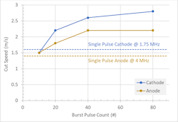
For the burst processing tests, the laser pulse repetition frequency (PRF) was fixed at 200 kHz and cutting results using burst sub-pulse counts ranging from 10 to 80 were obtained. Single-pulse processing was done at several different PRFs to determine the maximum cutting condition and set a baseline for comparison. Metrics for evaluating results included the maximum cutting speed and the extent of coating pullback.
Figure 3 summarizes the cutting speed test results. It clearly shows that burst-mode cutting speeds surpass single-pulse cutting speeds for all but the very lowest burst mode sub-pulse counts. Peak cutting speeds of 2.2 m/s and 2.8 m/s for the anode and cathode, respectively, were obtained using 80 sub-pulse bursts. This represents a 57% and 75% improvement in cut speed over single-pulse operation. This establishes that the USP laser can cut both electrodes at the rates required for commercial viability.
Cut quality was assessed by measuring the coating pullback for each set of cutting parameters on both foils. The data from this testing is quantified in Figure 4.
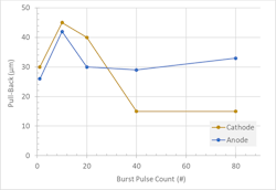
For both foils, there is an initial increase in pullback when processing with a 10-pulse burst compared to single-pulse processing (far-left data points). But as burst count increases, the amount of pullback is reduced. In the case of the anode foil, the single-pulse result still showed the lowest amount of pullback of all the test conditions, with the much faster-cutting 20-pulse burst condition only slightly larger.
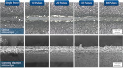
Optical microscope and SEM images of the cut edges were acquired to further inspect cut quality and visualize issues like metal smearing, debris generation, etc. These results are presented for the anode (see Fig. 5) and cathode (see Fig. 6) foils.
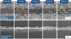
For the anode, the optical microscope images show cleaner copper foil surfaces—less debris and/or oxidation—with the 40- and 80-pulse bursts. SEM images show very little metal smearing at any of the conditions tested and the results look particularly clean for the 40 sub-pulse burst, which also coincides with the plateau of maximum cutting speed.
For the cathode foil, the impact of increasing burst sub-pulse count is more difficult to assess. There is clear smearing for the single-pulse process, and obvious successive improvement at 10- and 20-sub-pulse bursts. The amount of smearing appears to continue decreasing for 40- and 80-sub-pulse bursts. These images do have lower contrast, which makes it difficult to accurately gauge the degree of smearing. The overall trend with increased burst pulses is static or slight improvement in foil edge quality and a pronounced reduction in coating pullback.
It is widely accepted that USP lasers deliver superior processing quality compared to other laser types and alternative non-laser technologies for a wide range of cutting and ablation applications. But USP laser processing is also regarded as slow and expensive and therefore reserved for only the most demanding processes in high-value applications.
Our results show that when USP lasers are operated using burst mode operation—especially the highly flexible form embodied in TimeShift—production cutting of coated battery foils becomes practical and economically feasible. In particular, this testing showed that single-pass cutting speeds in excess of 2 m/s are achievable, and that USP lasers yield high cut quality in terms of key battery industry metrics like coating pullback and debris formation.
EDITOR'S NOTE
During the LASER World of PHOTONICS trade fair in Munich, Germany, June 24-27, 2025, you can find the MKS Spectra-Physics team at booth 314 in Hall A3.
About the Author

Jim Bovatsek
Jim Bovatsek is a senior manager of applications engineering at MKS Spectra-Physics industrial applications laboratory in Milpitas, CA. He has focused on laser applications development using nanosecond, picosecond, and femtosecond pulsed lasers since 2000, with various publications and patents having been generated. He holds a Bachelor of Science (Physics) degree from the University of California, Santa Barbara.