Improved automated fiber placement with a fully reflective top-hat shaper
In recent years, environmental considerations, and the need to reduce fuel consumption, have led the aeronautical industry to include increasingly more composite material assemblies in aircraft. Composite materials provide the benefit of having a lighter weight for the same mechanical strength as compared to metallic materials.
The Airbus A350 is a typical and pioneering example, with more than half its primary structure composed of composite materials. As a result, the need for a process to manufacture large, complex geometry composite parts in an efficient and repeatable manner has emerged. To a lesser extent, this need has also emerged in other industries such as the manufacture of wind turbine blades.
One process that meets this need is automated fiber placement (AFP). With this in mind, Cailabs has developed an ultracompact laser fiber placement head in accordance with the bill of specifications of Coriolis Composites, which has been integrated into AFP machines. It enables manufacturing composite parts with complex geometries while ensuring their good quality.
What is AFP?
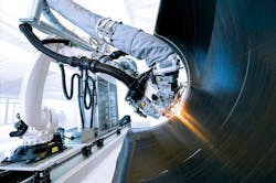
AFP is a sub-family of additive manufacturing involving the successive placement of fiber tapes on a mold to generate a composite part (see Fig. 1). The tapes are then fed from a spool via a robot arm and applied to the mold cavity, or to the plies already placed, with enough consolidation force to ensure bonding between the layups. It is often necessary to heat the tape and by extension the substrate during application. Some machines can simultaneously lay out several tapes, which can be cut independently in various positions.
There are also different types of molds: male or female. The process is compatible with different types of materials—thermosetting or thermoplastic resin prepreg fibers, as well as dry fibers. Also, unlike the more conventional techniques, this method does not require an autoclave; the prepreg fibers are cured directly on the mold, and the dry fibers can be infused or injected with resin using low pressure transfer.1, 2
This technique offers certain advantages over conventional methods. With small radius of curvature, the robot arm can lay out tapes on molds of complex geometrical shapes within the machine build volume. Automating the process makes it repeatable and helps reduce material losses, for example, by optimizing the length of the deposited layups.
Laser: a relevant tool for heating composites
When using thermosetting resins with a polymerization temperature of 200°C, it is possible to heat the composite tape using infrared lamps. However, they are not powerful enough for thermoplastic resins, which require higher processing temperatures (between 300° and 400°C). The use of thermoplastic resins is growing since it offers some advantages: they are recyclable and can be reworked during the process, at the cost of a higher glass transition temperature. The laser is therefore a suitable solution for heating the tapes. It can deliver high power on a limited surface and in a directional way. This provides all necessary power densities for processing thermoplastic resins at a suitable application speed.
The shaping of the laser beam heating the fiber allows it to adapt to the geometry of the area to be heated, and to improve the quality of the bond between the layups. Indeed, Mazumdar and Hoa showed a predominant effect of laser power (79%) on the bond quality.3
Developing a laser fiber placement head
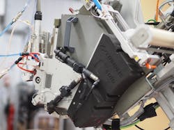
Cailabs developed a laser beam shaping solution for Coriolis Composites, designed specifically for its C-Solo AFP machine (see Fig. 2). Coriolis Composites is a French company specializing in automated manufacturing processes for composite materials, particularly through the design and manufacture of AFP machines. A laser head, based on Cailabs’ Multi-Plane Light Conversion (MPLC) technology, was designed to generate a rectangular beam of the confidential dimensions required by Coriolis Composites. The beam is shaped to provide a homogeneous energy profile, like a top-hat profile in both dimensions (length and width).In addition to this need for shaping, the laser head had to satisfy strong requirements in terms of size and mass. The compactness of the module makes it possible to reduce the size of the robot arm and thus the layup of more curved parts. The mass constraint is also important because the module is mounted on moving parts of the machine. A lower mass allows for a more precise and faster positioning by reducing the inertia of the robot arm. The laser head is therefore ultracompact with an overall size of 127 × 94 × 70 mm3 and a weight of 1 kg, of which about half comes from the standard Precitec connector. This makes the head compatible with female molds with small radius of curvature, often preferred to male molds for certain aeronautical applications.
The low power specification allows measuring the beam stiffness according to the two dimensions of the rectangle. This measure is defined as the ratio of the transition zone from 10% to 90% of the maximum intensity over the tray width at 90% of the maximum intensity. Thus, the module generated a shape with a stiffness equal to 0.14. Measurements have also shown the high homogeneity of the top-hat tray in both dimensions, a variation of 3.6% RMS on the small dimension, and 2.7% RMS on the large dimension.
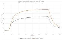
The high-power stability was also confirmed, with the cooling system bringing the optics to an acceptable steady-state temperature in 3 minutes (see Fig. 3). The optical module also provides a large depth of field, over ±15 mm. The shape remains rectangular with a top-hat profile throughout this range, and even beyond, with an increase in shape dimensions of only ±3%. High power tests were also conducted at different working distances (up to 295 mm, compared to 240 mm under nominal conditions).Results
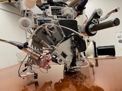
Therefore, the solution provided by Cailabs meets the specifications submitted by Coriolis Composites for integration on the C-Solo machine. The shaping module was connected via an LLK-D connector to a Laserline LDM 6000-100 diode laser (900–1080 nm) delivering a continuous power of 6 kW, and integrated to the mechanical interface of the machine and its cooling system (see Fig. 4). In order to satisfy the space restrictions, a thick optical prism deviating the beam by a 17.5° angle was added to the module output. This resulted to an output beam tilted with respect to the system, making the machine/shaping system assembly even more compact.This allowed the layup of 1.5 in. wide thermoplastic resin prepreg tapes, at a layup speed of up to 1.2 m/s at a temperature of 380°C on 2D surfaces, paving the way to concave or convex panels with double curvature. This module allows delivering a stable, robust, flexible, and precise heating process, while maintaining a small footprint. The homogeneity of the intensity profile also preserves the quality of the parts, ensuring a better adhesion and cohesion between the layers. Moreover, the high quality of shaping prevented the formation of any resin drips.
REFERENCES
1. O. Baho, G. Ausias, Y. Grohens, and J. Férec, Int. J. Adv. Manuf. Technol., 110, 7–8, 2105–2117 (2020).
2. See https://bit.ly/3yvuOyF.
3. S. K. Mazumdar and S. V. Hoa, Composites, 26, 9, 669–673 (1995).
About the Author
Julien Bayol
Assistant Product Manager, Cailabs
Julien Bayol is assistant product manager at Cailabs (Rennes, France).


