Future-proofing laser systems for medical device manufacturing
Medical device manufacturing and laser technology align in many aspects, encompassing quality and fine precision. Over the years this has been a mutually beneficial partnership, with laser technology enabling medical product innovation and medical device industry growth rewarding vendors.
Process value-add and production rate are evaluated against system price when considering the return on investment (ROI) of a potential system purchase. Looking forward, this is shifting to include the user software, setup standardization, production data, and automated parts handling—all to maximize production value-add.
A ‘user-friendly’ interface
What really defines a user-friendly graphical user interface (GUI) or, perhaps more accurately, great user experience? The benchmark use case is the smartphone, which almost any person of any age and any language can pick up and use. In manufacturing, this translates to using operators that require little to no training and can be rotated between systems. For engineers who have a dozen systems from a dozen vendors, they can instantly use and access administration-level functionality without having to learn yet another operating software. And, when an issue arises, not having to re-learn, saving time for these most valuable personnel.
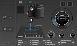
The key word from the GUI acronym is “graphical.” Graphics can provide on-screen representations of the system, enabling quick identification and selection to drill down to show each parameter that can be adjusted, but more importantly a pictorial guide explaining the parameter function. Figure 1 shows a screenshot of such an interface for a focus head that has enhanced wobble capabilities. Firstly, it is clear what piece of equipment in the system is to be changed; next, there is a depiction of what each parameter is; and finally, where the selected value is within the adjustment range. Course and fine adjustment are adjusted on a touchscreen that can be fixed to the system or a removable tablet.
System setup standardization
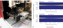
For any system, be it a point-of-use single part or a flexible cell with many different parts, the time taken to verify the machine is set up correctly at the start of a shift or job can add up over time. This is even worse if the setup process is done incorrectly. For laser processing, the biggest offender is the position of focus, knowing where it is and maintaining the optimal position. Rather than rely on qualitative testing on coupons, a highly accurate one-and-done quantitative camera that images the beam profile provides exact focus location. Figure 2 shows the measurement system and subsequent beam profile identifying focus position.For flexible cells, particularly for welding, changing the size of the spot for different parts is usual. The quick fix is to purchase optics that provide the smallest spot size that will be needed and then de-focus to enlarge the spot. The problem with this, evident from the beam cross-section in Figure 2, is that moving out of the focus position provides zero depth of focus or z tolerance. Instead, a programmable expander/collimator can be used to adjust the spot size with suitable resolution with a range around 2–3X the minimum spot size and maintains the focus position in the same z location—again, a quantitative device that enables the focus spot size to be precisely controlled, known, and programmed.
Production data
In recent times, the creation and interpretation of production data has been captured by “Industry 4.0”—a phrase coined nearly 10 years ago by a German high-tech strategy group when considering the impact of cheap computing power to enable optimal production underpinned by machine learning. While we are still navigating the implementation of Industry 4.0, progress is being made—the first step is data collection.
Many parts of a system, including the laser, beam delivery, focusing optics, stages, tooling, and gas delivery, can all be monitored. As a first level, this is a process start verification with a Yes/No outcome—for example, do we have shielding gas? Is the part correctly loaded into the tooling? Over time, this data can be used to set operational ranges for parts of the system where that applies, such as laser power and cover-slide cleanliness, and setting stack-up logic where, say, three parameters are within their operational window, but added together push the process out of specification. Trying to figure this out manually or with unwieldy statistical control software is a challenge, so machine learning can accelerate this process and provide more insight with the same dataset. Predictive failure, planned downtime, and a system that schedules its own maintenance are all possible. However, this is only half of the story—what about measuring the actual process itself?
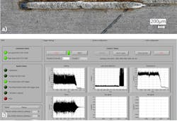
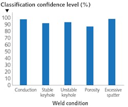
Let’s consider laser welding: the only way to be 100% certain a weld is OK is to pull it apart to verify mechanical strength and cross-section integrity, which is not so great for production yield. The second-best approach is 100% visual inspection by a trained person. The goal for a process monitor is a reliable Good/No Good output, as well as predictive failure to reduce inspection costs, scrap, and unplanned downtime. Process monitoring for laser welding has been available for some time, though largely for multikilowatt welding in automotive. Their limited uptake in medical devices can be attributed to a lack of ROI—if the system isn’t so suited to microwelding and does not reduce inspection costs or scrap, then it is acceptable as an R&D tool, but not for production.Automated parts handling
The generally small and delicate parts in medical devices, plus relatively low production numbers compared to other industries, provide a cost and feasibility barrier to adopting automated parts handling. However, rather than thinking about highly complex production lines, local system parts handling can provide islands of automation to drive down production costs and enable production in high-labor-cost regions with better oversight.
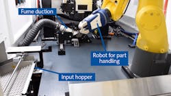
There are many odd part shapes in medical devices—however, there also is a lot of tubing. Let’s start with the low-hanging fruit of short lengths of metal tubing that are used in a variety of end products; in this case, either marking or micromachining the part. Figure 5 shows the internals of the system that comprise a vibratory fed pick station for the robot. This system can hold more than 1000 tubes, which would typically translate to hours of production. The robot then loads the tube into the collet, verifies the protruding length, and readjusts if necessary. Processing occurs and then, based on post-part inspection, places the completed part into the good/no good bin. For this system, the range of tube lengths varied from 2.5 to 14 in., with 0.12 in. diameter.
Summary
Laser technology in medical device manufacturing will continue to grow, with the industry likely increasing in uptake as unique process capabilities enable more challenging product designs. Perhaps the greatest innovation will be on the production value-add side through these system innovations to maintain alignment with the production environment, as well as driving further growth of laser technology.
About the Author
Geoff Shannon, Ph.D.
Director Strategic Marketing for Precision Manufacturing, Coherent
Geoff Shannon, Ph.D., is Director Strategic Marketing for Precision Manufacturing at Coherent (Santa Clara, CA) and an Editorial Advisor to Industrial Laser Solutions. He previously served as Laser Technology Manager for Miyachi Unitek, specializing in the development of lasers and applications for existing and new markets. Shannon has a BEng in Mechanical Engineering and PhD in Laser Welding Technology from the University of Liverpool. His 20-year career in laser technology has centered around applications research and development and new product development of lasers and systems.
