Laser cladding offers wear protection for knife seatings
URSULA HERRLING-TUSCH
Every day in the timber processing industry, countless logs up to 22 m in length are debarked, measured, and processed into lumber. The extreme stress on the production line equipment and tools used for this process is something on which Gebr. Eigelshoven GmbH & Co. KG, a state-of-the-art sawmill in Würselen, Germany, can comment. When it comes to repairing heavily worn circular knife tool-holding fixtures, their solution is laser cladding performed by Pallas GmbH & Co. KG, which specializes in the repair of highly stressed components.
Eigelshoven, founded in 1887, handles a daily throughput of 1000 cubic meters on the bandsaw. Currently, they process 80% spruce and 20% Douglas fir. About 50% of the mill’s customers are located in Germany, 30% in the Benelux countries, a further 10% in France and Great Britain, and the rest abroad. The company has a reputation for the high quality of its processing and treatment, for tightest dimensional tolerances and consistently high surface quality.
From tree trunk to structural timber
Logs are delivered to the log yard, where they are separated and the trumpet-shaped end of the log is milled down. They are then debarked and inspected for metal splinters, nails, or munition. After logs are laser-measured to establish their length and diameter, as well as any special features like warp or ovality, these measurement data are then assigned to the customer orders in the next stage, the cross-cutting station. This computer-based process determines which lengths of which logs are to be cross-cut for which customer orders. Logs go to the sawmill, where the complete customer order is loaded into a quadroline mill—four bandsaws with a magnetic guidance system. In an inline process, each log then passes through the 80-m-long and 15-m-wide bandsaw line at a feed rate of 28 to 105 m/min. On the basis of the previously established optimal cutting plan, the log is then automatically rotated into its correct orientation.
In the next stage, a chipper canter removes two opposing curved sides of the log. The circular knives used for this process are held in tool-holding fixtures. By means of a computer-aided nesting plan, the bandsaw then cuts the product from the middle of the log according to the customer’s order, and also makes further useful cuts from the rest of the material.
In the next stage, the log is rotated through 90° and a second chipper canter removes the other two curved sides, resulting in a rectangular block of wood. This is then divided into boards by a variable circular saw with one horizontal and six vertical axes. In the sorting unit, unusable pieces are sorted out and then stacked and banded for delivery to the customer. Finally, the cut-to-size lumber passes through a range of finishing stations: planning exact truncation with millimeter precision, fully automated six-axis processing (joining), bath impregnation, and drying.
Tool fixtures set the pace
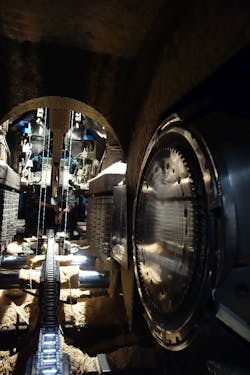
A throughput of 1000 cubic meters a day creates extreme stress for the circular knife tool-holding fixtures in the chipper canter. This is where the rough surface of the log, with residual bark, irregularities, or branches, is milled to an even surface. The roughness is ablated by four 15 × 28 cm knives fixed into a cast-iron rotor disk that measures 750 mm across and 300 mm thick. Another four smaller knives—measuring just 7 × 7 cm—are deployed for the smoothing action. These are attached to the rotor disk by means of rectangular tool-holding fixtures (FIGURE 1).
The knives are exchanged every day—just like all the mill’s saw blades—and resharpened in Eigelshoven’s own grinding shop. When it comes to cut quality and speed, the seatings that hold the small knives in the cutters in the rotor disk are of critical importance. The wear and tear due to constant friction tends, over time, to create damaged spots on the right and the left of the tool clamping. Wood gets into these recesses and renders the cut unusable due to torn-out bits of wood fiber. At the same time, the performance of the machine is diminished, and this puts maintenance of the required daily throughput at risk.
In view of the high costs involved in replacing one of these tool holders, Rainer Oprei, Technical Director at Eigelshoven, has long been on the lookout for a durable repair option, as the mill has a total of four of these rotary cutter heads in operation on a daily basis. But he was skeptical, due to bad experiences with initial repair attempts, as to whether such a durable repair option even existed. Then, he witnessed the success that Pallas achieved in its treatment of several shafts with bearing damage, and this encouraged him to give the idea another try.
When one of the tool holders had to be replaced due to wear and tear, he turned to Pallas, which suggested a surface reconstruction of the damaged structures by means of laser cladding. Using strictly localized heat input, this generative process facilitates high-precision surface coating with minimal warpage. The coating material is applied through concentrically arranged nozzles to the surface area to be treated and melted together with the base material. In this so-called melt pool, the two materials join metallurgically into a dense coating with low dilution. Moreover, the near-net-contour quality of the applied coating means that post-processing costs are kept to a minimum (FIGURE 2).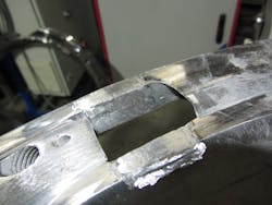
Point by point to success
One particular challenge that Pallas faced was that the tool holders were worn to different degrees. The hardness in the worn areas also had an extremely inhomogeneous distribution, with differences in hardness of up to 40 HRC. For this reason, Pallas decided to experiment on all four tool-holding fixtures with different working materials that had differing corrosion resistance and material hardness grades ranging from 50 to 63 HRC. However, the heterogeneous surface condition of the worn tool-holding fixtures did not permit any continuous coating with high-speed steels, which meant that more manual processing would be needed (FIGURE 3).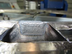
Rodion Honisch, Head of the Laser Division at Pallas, developed a modular program to be used for the task with a 6 kW Laserline diode laser with a wavelength in the near-infrared range, 900–1030 ± 10 nm, operating in both continuous-wave and pulsed operation. This allowed him to adapt the laser pulsing to the specific configuration of the worn area. Pallas developed the laser hardening process and installed the laser equipment.
In this way, he could choose where to begin with the reconstruction, on the flanks or on the lower edge. In laser pulsing in very short controlled bursts—the laser only flashes for just 200 ms—energy is applied selectively to the material in order to repair complex geometries point by point. Thanks to the near-net-contour quality of the process, the coated tool-holding fixtures required only minimal post-processing, which was done with a Dremel. All in all, the repair of each tool clamping took at least eight hours (FIGURE 4).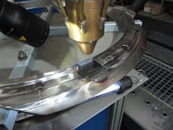
No wear after a year of continuous operation
Oprei installed these repaired circular knife tool holders in one of the sawmill’s chipper canters in order to test the durability of the laser cladding under the tough conditions of the machine’s daily operation. One year later, he examined the wear and tear and was surprised that only one of the four knife seatings, which had been processed by Pallas, showed no signs of wear and tear at all, while the other three had only infinitesimal traces. Normally, after a year in operation, circular knife tool holders are completely worn down. Oprei commissioned Pallas with the repair of a more-worn circular knife tool holder, this time using the particular working material that had proved itself best in the first repair.
For Pallas, the follow-up order also meant having to find a way to reduce the required manual processing in order to ensure the cost-effectiveness of the repair for both sides. The problem lay in the form of the knife seating, which impeded a suitable positioning of the laser head. In view of the wear pattern, Rodion Honisch, Head of the Laser Division, decided to homogenize the surface to be treated by first milling out the wear points. The milled-out recess—up to 7 mm deep—had to be designed so that the applied reconstruction coating would meld firmly enough to the base material. Because the knife seating was extremely worn, his first step was to create a slightly raised connecting edge of austenitic stainless steel 1.4404 (316L), on which he then reconstructed the worn basic structure of the tool-holding fixture. On this, he then applied high-speed steel with a hardness grade of 63 HRC as wear protection.
This surface-treated cast-iron rotor has now been back in operation at Eigelshoven for a month. Oprei is confident that it will more than fulfil his expectations of a long service life, and he is full of praise for the “enthusiasm with which Pallas took on this task, and their willingness to take risks.” The positive result and an 80% saving on costs compared to buying a new unit also spoke for the chosen solution. Optimal preconditions for the sawmill to entrust the surface engineering experts with a new—and by no means less challenging—task. The bed knives on the hacker will be given durable wear protection by means of laser cladding.
URSULA HERRLING-TUSCH ([email protected]) is a specialist journalist for Pallas GmbH & Co. KG, Würselen, Germany; www.pallaskg.de.